Week 4- Challenge
Aim :
Creating 1D element in hyperworks
Objective :
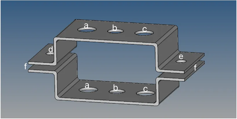
Create 1D elements on the following component with given cross-section and DOF
- Rod element:- with only translational DOF and RBE2 link
Cross-Section: BOX- Dimension a= 12 mm
dimension b=10 mm
Thickness t= 0.75 mm
- Beam element:- with all DOF and RBE3 link
Cross-Section: I Section- Dimension a= 8 mm
Dimension b= 10 mm
Dimension c= 8.5 mm
Thickness t1= 0.75 mm
Thickness t2= .6 mm
Thickness t3= .6 mm
- Bar element:- with only x and y DOFs With RBE3 link
Cross-section: CROSS section- Dimension DIM1= 5 mm
Thickness DIM2= 1.2 mm
Dimension DIM3= 10 mm
Thickness DIM4= 1.2mm
- & e. apply the mass of magnitude 10 with RBE2 link
- Join the two components with Spring elements
 \
\
Procedure :
STEP1-Importing the model to hypermesh and creating the mid surface
The current model is the parallel bracket which is an IGES file. The IGES format means that it is a surface model and as such has no mass property information. So the model is imported to the workspace.
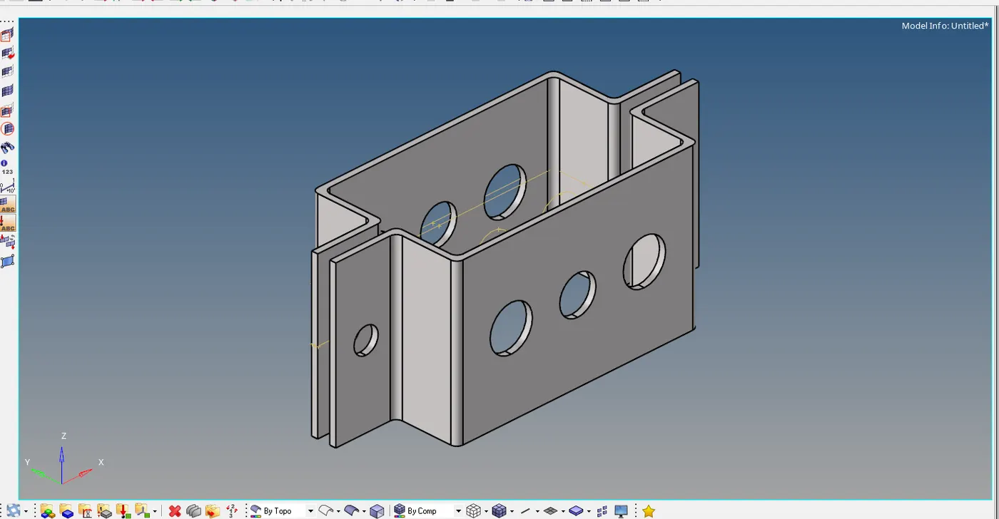
fig-given CAD MODEL
Mid surfacing:
Now to extract the midsurface we will be proceeding with the AUTOMATIC MID SURFACE extraction. This so because the model is pretty simple having the uniform thickness throughout the geometry.
MIDSURFACE>AUTO EXTRACTION .
By selecting each bracket one at time the midsurface is extracted easily.
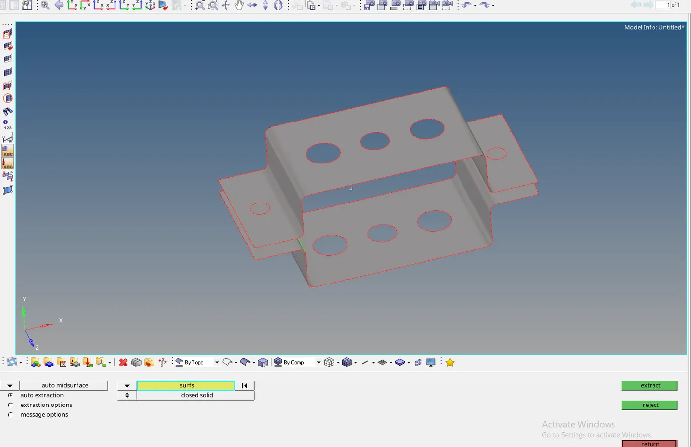
Fig- Mid surface extracted.
Organizing :
Now the mid surface extraction is stored as a single component under the component id. Now we can create the separate component id for each bracket by using the ORGANIZING option.
Create the component id by naming it as bracket 2
Go to TOOLS>ORGANIZE. Set the current component as BRACKET2 .
DESTINATION>select bracket2 >move
Both the mid surface now have their separate component id. We can change the color of both the components from the TAB box and rename them likewise.
STEP2-Creating the property id and material id:
We can create property for the brackets but first we have to create the material id
Create > material > card id > mat1
Mat1 is associated with the steel material.
Now after creating the material id we can create the property id for each brackets.
create>property > bracket1>material id > steel> thickness> 5(original part thickness)
Likewise creating the id for the bracket 2 also. These two properties now have to be assigned to the component id of the brackets so that the final element model has the thickness.
components>Bracket1>propertyid> bracket1
STEP 3-Generation the mesh and deploying the 1D element.
Washer split:
It is good practice to provide the washer split around the hole region to avoid the formation of tria elements. Washer split helps to create the similar parallel edges that in turn create the quad elements around the hole. Quad elements give the accurate results in the simulation.
GEOMETRY>QUICK EDITS >WASHER SPLITS
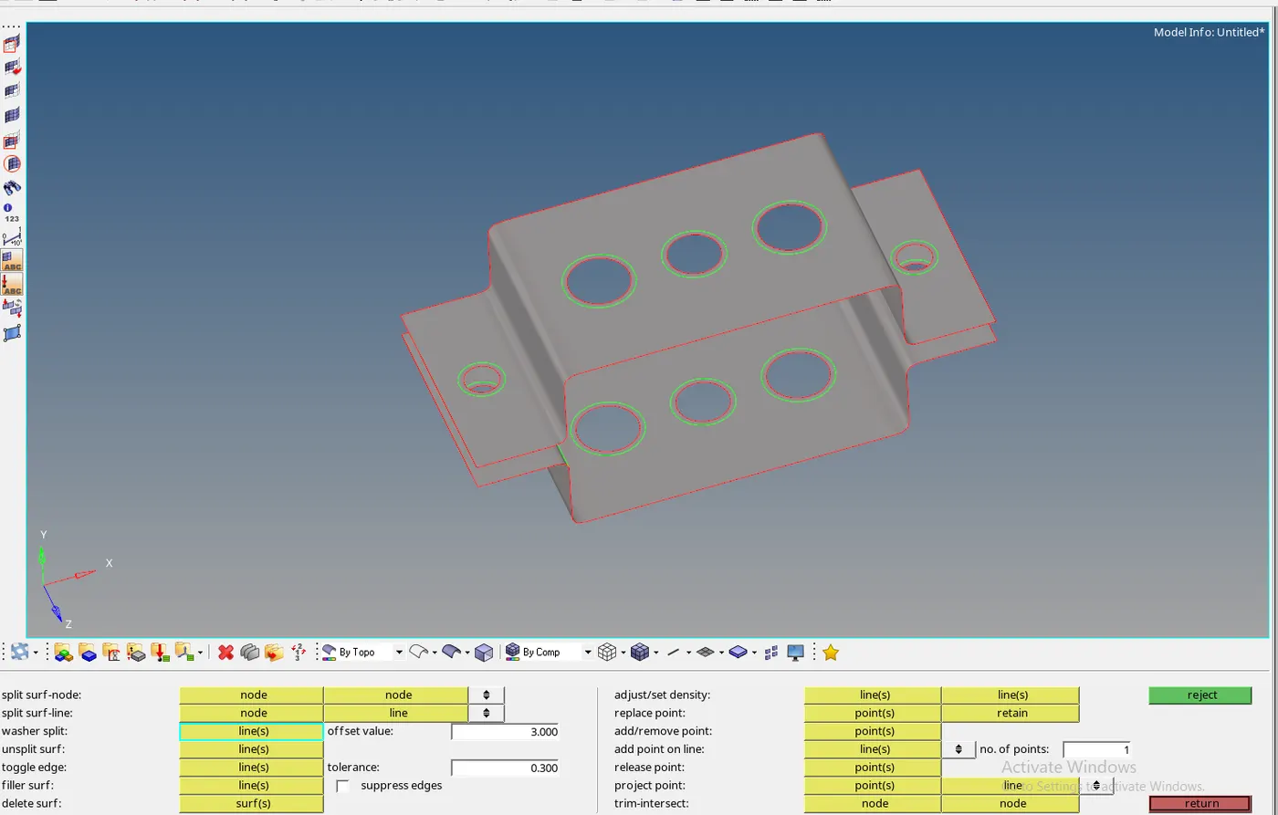
Fig- washer split around the holes.
Meshing:
The mid surface extracted has to be deployed with the 2D mesh because for deploying the 1D connection we need only FE or elemental model. For generating the mesh we will be going with the AUTOMATIC MESH method. Model is simple with less complicated areas so the hypermesh will be giving pretty good mesh flow .
AUTOMESH >selecting the surface > size as 5
We can go with higher element size but the mesh element will not be able to capture the fillet areas.
Tria elements can be eliminated around the holes by setting numbers of node on hole edge and washer as equal.
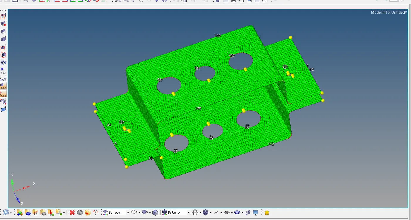
Fig - mesh deployed using the mixed element.
STEP 4-Deploying the 1D elements
Rod connection :
For providing the 1D element we have to first rigidized the hole with the required degree of freedom. The holes are rigidized by deploying the RBE2 links(RIGID BODY ELEMENT TYPE2).
1D>rigids> selecting the nodes
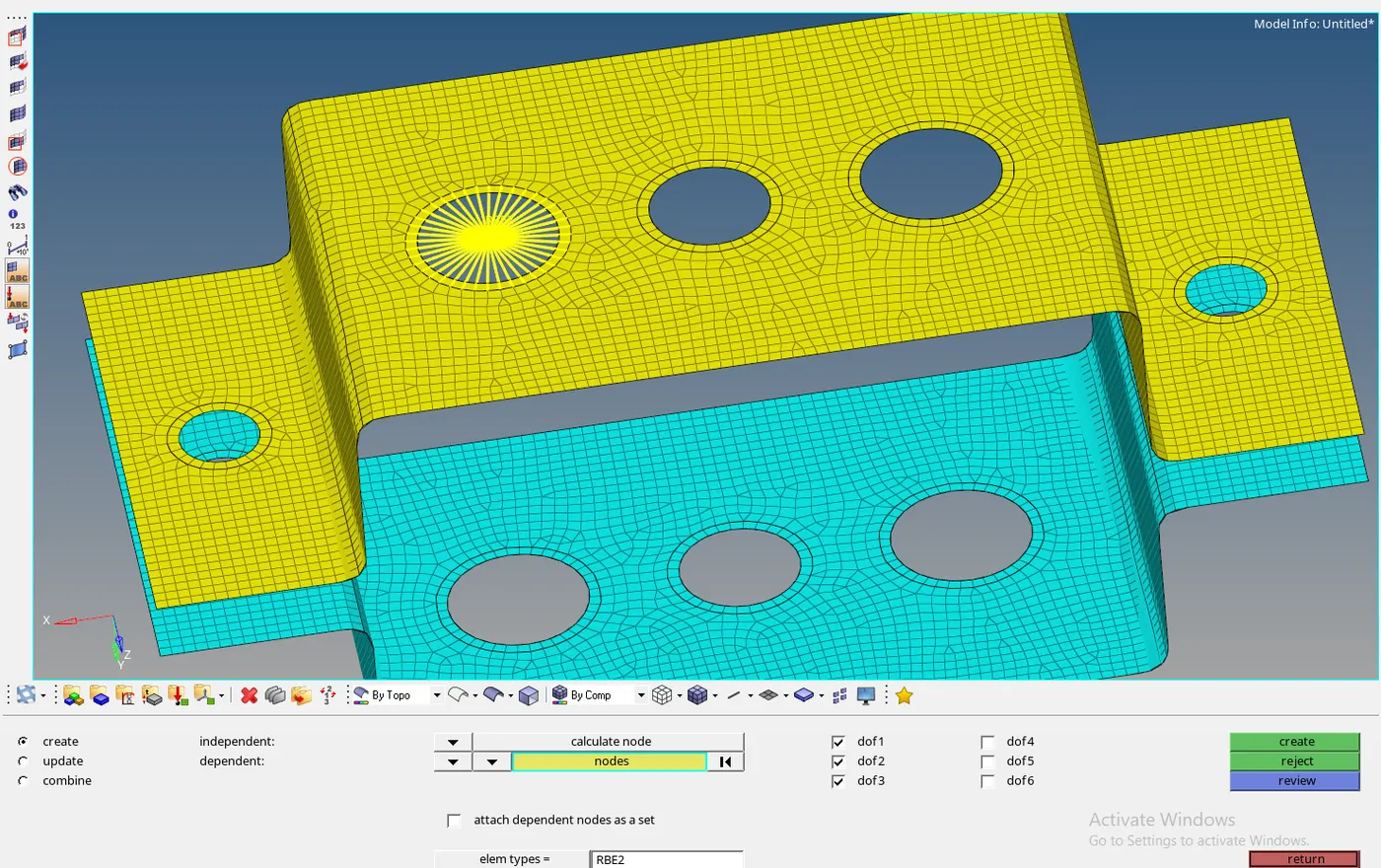
Fig - deploying the rbe2 connection with only three DOF.
The nodes are selected along the path from hole and washer splits. The advantage of the RBE2 connection is that all the nodes shares the equal amount of loads.
Since the first ROD ELEMENT has only three DOF in translation direction, we can constrain the rest rotation motion.
Opposite hole is also deployed with the same process.
To deploy the rod connection we have to choose the connection type as ROD. Rod is the symmetrical element which only transmits or supports translation loads.
1D>rods> create > choosing the element type as CROD.
Selecting the centre nodes of the opposite holes connection is developed as a rod element.
Beam connection:
Beams are asymmetrical cross section members that can transmit loads in all directions. To represent the beam connection we are using the RBE 3 links for the other hole. RBE3 elements are different from the RBE2 since the load shared by all the nodes is not equal. The node closer to the independent node will have more load than the node that is further.
rbe3>selecting the node > all DOF ( as given)
Now to develop the beam connection between the two holes we are choosing the element as bars. Since the only difference between the bar and beam is that bar is a symmetrical member while the beam is asymmetrical.
bars>element type as CBEAM >selecting the node centre > selecting the direction nodes.
Bar connection :
As said the bar is a symmetrical cross section member which supports load in all directions. To deploy the connection.
rbe3>nodes selection> only x and direction dof (given)
The opposite node is rbe3 connection can be deployed as above. Now to connect the holes by bar , we have to select the element type as CBAR.
1d>bars>element type cbar> node selection > bar direction > ok.
Spring connection:
To deploy the spring connection the last two holes have to be first deployed as RBE2 connections. The rigids connection can be deployed using the 1D > rigids .
We have to assign the mass of 10 to these elements. To do that
1D> masses> 10 > select the nodes.> ok
To attach the opposite node by spring we go to
1D> spring> select node > select element type as CLESS1.
Now all the required 1d elements have been deployed to their respective locations.
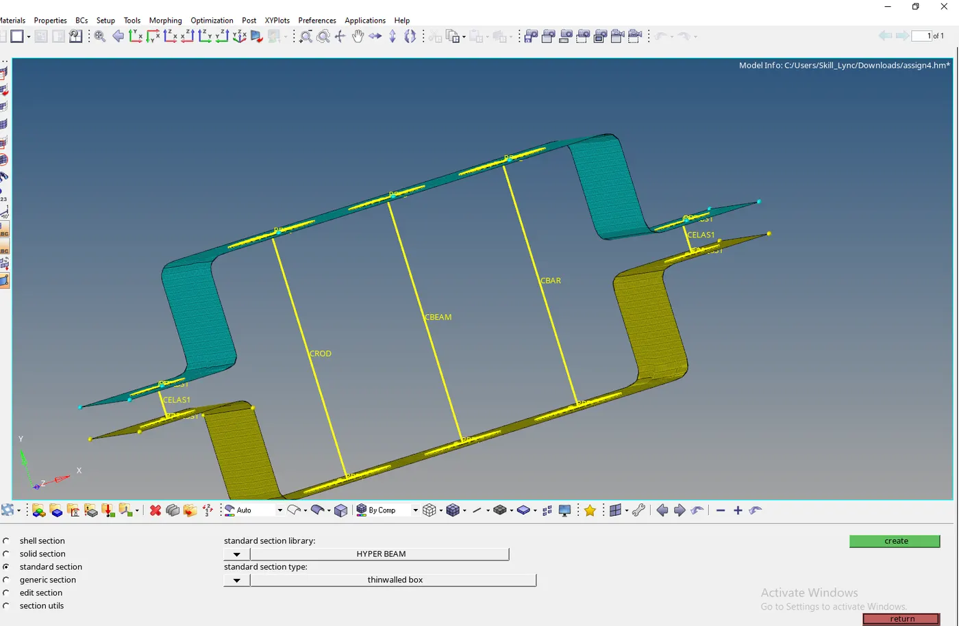
Fig- deployed 1D connection.
STEP 5-Defining the cross section and property:
All the above deployed connections are just the 1D elements and currently they don't have any property and cross section.
Cross section :
To actually represent the all the 1D element connection we have to define the cross section of each element. Cross section can be defined using the HYPERBEAM command that helps to create the cross sections. It has some predefined cross section type as T,I,BOX, SOLID CIRCLE, H etc.
1D>hyperbeam> standard section > hypebeam > section type
After selecting the cross section type the hyperbeam window opens where we can define the size of the cross section. We can create all the crossection in the hyperbeam window for the respective elements.
The all created cross section are stored under auto beam section collectors in the TAB bar of main workspace.
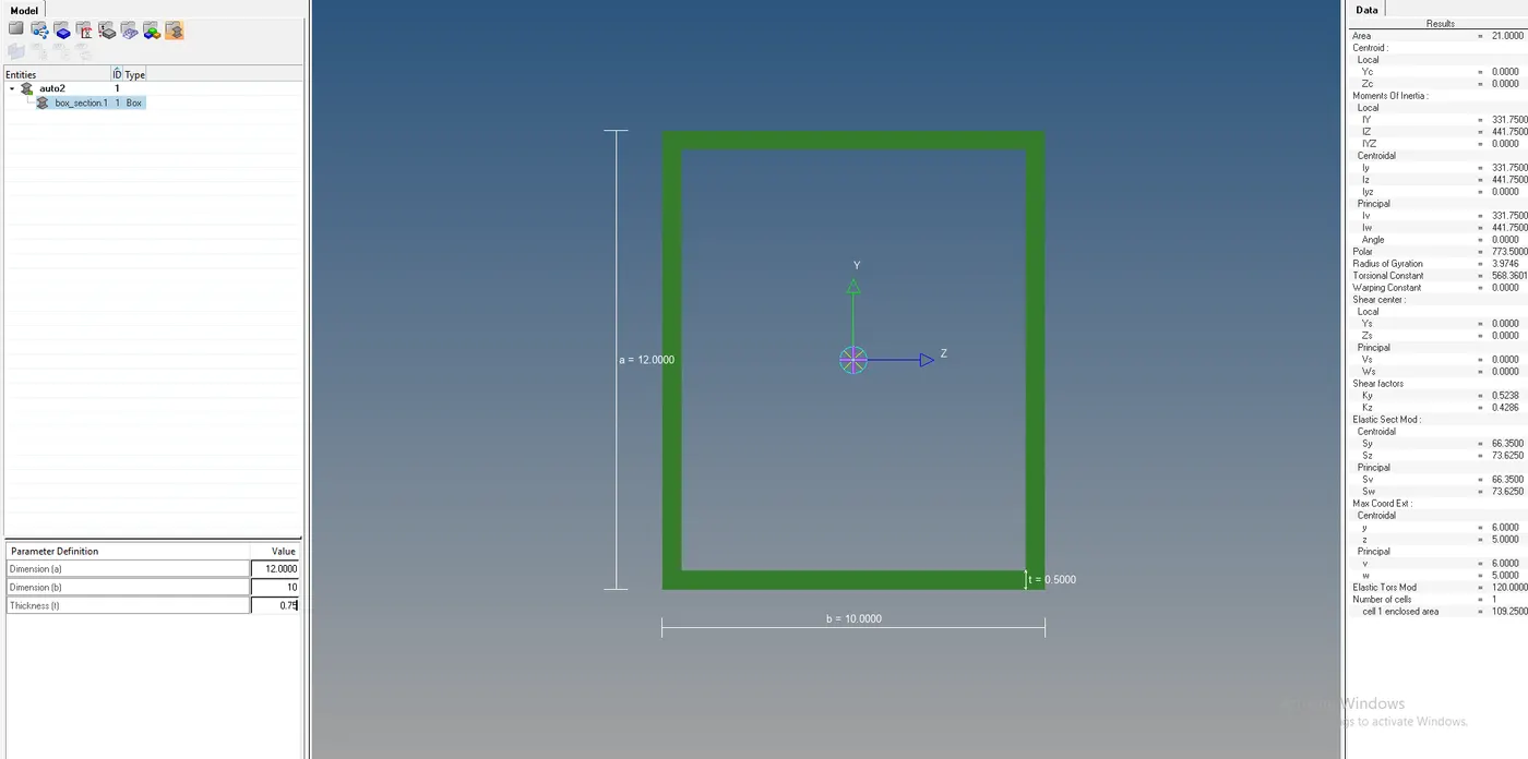
Fig- thinwalled box for rod element
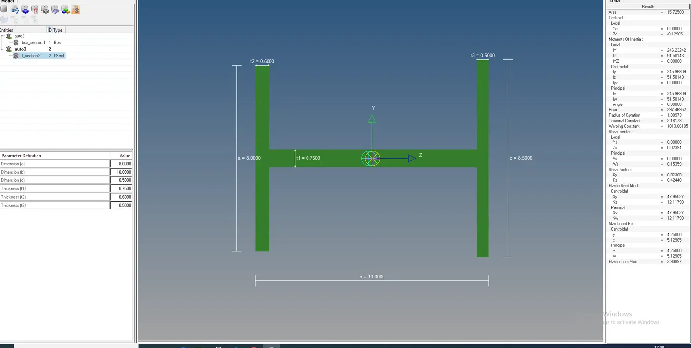
Fig-i section for beam element
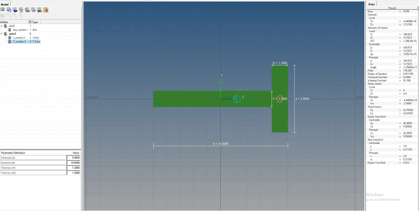
Fig- cross section for the bar element.
Property :
In order to apply these created cross sections to 1D element we have to create the property id card for the all the three elements. To crete the property id
Tab bar> right click >create> property> bar, beam , rod
Creating the separate property id for each element.
- Bar property > card id > pbar> beam section > T section .
- Beam property id> card id>pbeam> beam section> i section
- Rod propertyid >card id>prod> beam section> thinwalled box
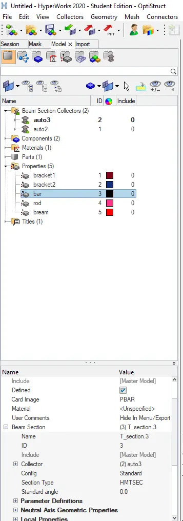
Fig- property id for elements.
Assigning the property to elements :
To actually assign all these properties to the elements we have to update all the information for each element.
1D>bars>update> property > bar> element type > cbar > update
1D>bars>update> property > beam> element type > cbeam > update
1D>bars>update> property > rod> element type > crod > update
The above set of commands will assign the cross section to the respective elements. To visualize it we can switch on the 1d elements to the shaded detailed representation.
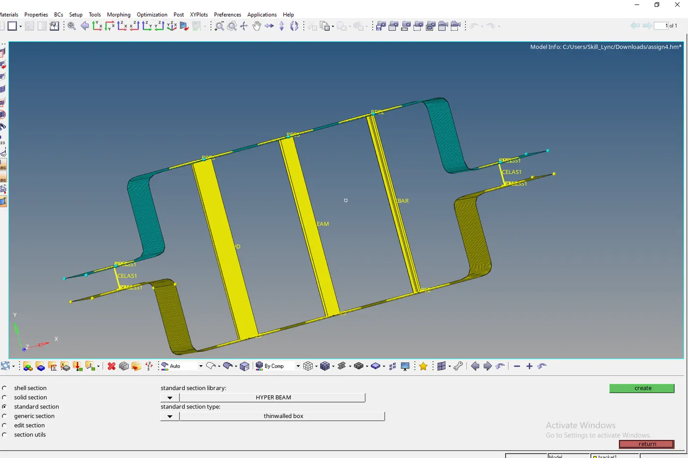
Fig-crosection for the 1d element.
Results:
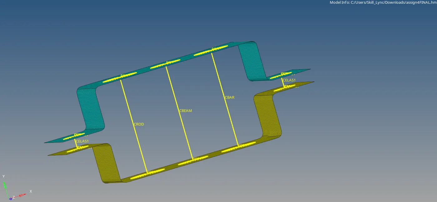
Fig-Final bracket with 1D connection.
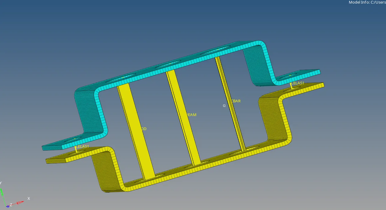
Fig-final Bracket model with 1D elements after assigning the thickness.
Conclusion:
The parallel bracket model is deployed the quality mesh and also all the 1D connection including rod , bar and beams with the required degree of freedoms and elements type.
link for the model - https://drive.google.com/drive/folders/1DsNiiuRj477inBSDuCY7Oz8cBjcEbuRG?usp=sharing