Week 4 Challenge
Aim:
To understand the concepts in analysis and design of flexural members like beam, girders, etc.
Introduction:
Flexural members like Beams are structural members that support transverse loads and are therefore subjected primarily to flexure, or bending. If a substantial amount of axial load is also present, the member is referred to as a beam–column.
Design of Beams
- Section classification problem for listed beam shapes
Calculate section classification of following beam shapes
1) ISMB 500
Section classification:
Taking fy = 250MPa
For ISMB500
b = 180mm
d = h – 2(tf +R) = 500 – 2(17.2 + 17) = 431.6mm
ɛ = (250/fy)1/2 = (250/250)1/2 = 1
b/tf = 180/2x17.2 = 5.23 < 9.4ɛ
d/tw = 431.6/10.2 = 42.3 < 84ɛ
Hence the section is classified as plastic section.
2.ISMC 200
Section classification:
Taking fy = 250MPa
For ISMC200
b = 75mm
d = h – 2(tf +R) = 200 – (11.4 + 11) = 177.6mm
ɛ = (250/fy)1/2 = (250/250)1/2 = 1
b/tf = 75/11.4 = 6.58 < 9.4ɛ
d/tw = 177.6/6.2 = 28.65 < 42ɛ
Hence the section is classified as plastic section.
3)PG 1300 x 450 x 20 x 12
Taking fy = 250MPa
For PG 1300 x 450 x 20 x 12
b = 450/2 = 225mm
d = h – 2(tf ) = 1300 – 2(20) = 1260mm
ɛ = (250/fy)1/2 = (250/350)1/2 = 0.845
b/tf = 225/20 = 11.25 < 13.6ɛ=13.6x0.845=11.492
d/tw = 1260/12 = 105 < 126ɛ=126x0.845=106.47
Hence the section is classified as Semi Compact section.
4)Double angle (Back to back) – 2 x ISA 75x75x6
Taking fy = 250MPa
For ISA75x75x6
b = 75mm
d = h – tf = 75 – 6 = 69mm
ɛ = (250/fy)1/2 = (250/250)1/2 = 1
d/tf = 69/6 = 11.5 < 9.4ɛ
Hence the section is classified as plastic section.
5)RHS - 150 x 100 x10
Taking fy = 250MPa
For RHS 150 x 100 x 10
b = 100-(10x2) = 80mm
d = 150-(10x2) = 130mm
ɛ = (250/fy)1/2 = (250/250)1/2 = 1
b/tf = 80/10 = 8 < 9.4ɛ
d/tw = 130/10 = 13 < 84ɛ
Hence the section is classified as plastic section.
6)Builtup box – 1000 x 450 x 20 x 12
Taking fy = 250MPa
For BOX 1000 x 450 x 20 x 12
b = 450-24 =426mm
d = h – 2(tf ) = 1000 – 2(20) = 960mm
ɛ = (250/fy)1/2 = (250/250)1/2 = 1
b/tf = 426/20= 21.3 < 15.7ɛ =>> Slender
d/tw = 960/12 = 80 < 105ɛ =>> Compact
Hence the section is classified as Slender section.
- Effective length problems
Calculate effective length of rafter madeup of Builtup I section about major (x-x) and minor axis (y-y) having purlin spaced at 1.2 m.
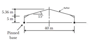
Length of Rafter = (202+5.362)1/2 = 20.71m
Ly = Minor axis effective length = 1.2m
Since, Purlin spaced @ 1.2m
Lz = Major axis effective length = 0.8L = 0.8(2x20.71) = 33.13m
- Deflection of a beam problem
- Calculate deflection at the centre of the beam shown below. EI = 20 x 106 Nm2
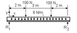
Deflection due to UDL = (5/384)wL4/EI = (5/384)*6x74/20x106 = 9.38 x10⁻⁶ mm
Deflection due to Point Load = (Fa/24EI)x(3L2 – 4a2) = (100x2/24x20x106)x(3x72 – 4x22) = 5.46 x10⁻⁵ mm
Where L = Total Length
F = Concentrated load
a = Distance from start of beam & point of application of load
Total Deflection = 9.38x10⁻⁶ mm + 5.46x10⁻⁵ mm = 6.398x10⁻⁵ mm
- Calculate deflection at the centre of the beam shown below. EI = 25 x 106 Nm2
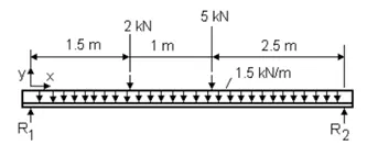
Deflection due to UDL = (5/384)wL3/EI = (5/384)*1.5x103x53/25x106 = 9.77 x 10⁻⁶ mm
Deflection due to Point Load of 2kN = (wL3/48EI)x(3a/L – 4(a/L)3)
= (2x103x53 /48x25x106 )x(3x1.5/5 – 4(1.5/5)3) = 0.000165 mm
Deflection due to Point Load of 5kN = (wL3/48EI)x(3a/L – 4(a/L)3)
= 5x103x53 /48x25x106 (3x2.5/5 – 4(2.5/5)3) = 0.00052 mm
Total Deflection = 9.77x10⁻⁶ mm + 0.000165 mm + 0.00052= 6.95x10⁻⁴ mm
- A simply supported beam is 10 m long with udl of 10 kN/m Calculate the Flexural stiffness (EI) of the beam which limits the deflection to 5 mm at the middle.
Deflection due to UDL = (5/384)wL4/EI
(5/384)*10x103x104 /EI = 5 x10⁻³ m
EI = 26.0417 x10⁷ Nm2
- Moment capacity determination problem
Select a standard hot rolled section for the beam which is simply supported of length 6 m spaced at 3 m c/c, carrying a floor Dead load of 5 kN/m2 (including Self weight) & Live load of 6 kN/m2 and a concentrated load of 100 kN at mid span of beam. The beam is laterally restrained and assumes bearing length of 50 mm
STEP 1:
Dead load = 5 x 3 = 15kN/m
Live load = 6 x 3 = 18kN/m
Assumed bearing length = 50 mm
Calculation of factored loads:
Dead load = 1.5 x 15 = 22.5 kN/m
Live load = 1.5 x 18 = 27 kN/m
Concentrated load on beam = 1.5 x 100 = 150 kN
Total UDL on beam = 22.5+27 = 49.5 kN/m
STEP 2:
Maximum bending moment = WL2/8 + WL/4
= (49.5 x 62 / 8) + (150 x 6 / 4) = 447.75 kNm
STEP 3:
Section modulus required (Zp)
Zp required = (M x Ymo) / fy = (447.75 x 106 x 1.1 / 250) = 197 x 104 mm3
STEP 4:
Choose a trial section of ISMB 500
Max. Deflection allowed = (Span/360) = 6000/360 = 16.67mm
To satisfy this deflection, Iz = ?
Deflection = ((5/384)*18x60003/2x105 x I) + (100 x 60003 )/(48x2x105 x I)
I = 150157 mm4
Section is OK
Section classification:
ɛ = SQRT(250/fy) = SQRT(250/250) = 1
b/tf = (190/2) / 19.3 = 4.922 < 9.4ɛ
d/tw = [550 - 2(19.3+18)] / 11.2 = 42.45 < 84ɛ
Hence the section is plastic section
STEP 5:
Adequacy of the section including self-weight of the beam
Factored self-weight of the beam = 1.5 x 1.037 = 1.5555 kN/m
Maximum bending moment = 299.25 + 1.56 x 62 /8 = 306.27 kNm
Zp required = (M x Ymo) / fy = (306.27 x 106 x 1.1 / 250)
= 1347.6 x 103 mm3 < 2711.98 x 103 mm3
Hence the section is adequate.
STEP 6:
Shear force V = (49.5x6/2) + (150/2) = 223.5 kN
STEP 7:
Design shear strength of the section
Design shear strength Vd = (fy/Ymo x √3) x h x tw = (250/1.1x√3)x500x10.2 = 669.2 kN
Also 0.6Vd = 401.52kN > 223.5 kN, Hence Safe.
The design shear force V<Vd
Step 8 :
Check for design capacity of the section
d/tw = 42.45 which is less than 67ɛ
Md = BbZp x fy / Ymo < (1.2 x Ze x fy) / 1.10
Bb = 1.0 since the section is plastic
Md = (1.0 x 2711.98 x 103 x 250)/1.1 = 616.36 kNm
< (1.2 x 2359.8 x 103 x 250) / 1.1 = 643.58
Hence the design capacity of the member is more than the maximum bending moment Md.
Check for deflection :
d = (5/384)wL3/EI + (WL3/48EI)
= (5/384)*5x103x60004/2x105x45200x105 + (100 x103 x 60003/48x2x105x45200x105)
= 0.0156 mm + 0.4977 mm = 0.5133 mm
Allowable deflection = L/300 = 6000/300 = 20 mm
Actual deflection is less than the allowable deflection.
Step 9:
Check for web buckling at support
Assume stiff bearing length b1=75mm
Depth of web d=465.6mm
Ieff web = (b1 x tw3)/12 = (75 x 10.23)/12 = 6632.55 mm4
Aeff web = b1 x tw = 75 x 10.2 = 765 mm2
r = √(Ieff web / Aeff web =√(6632.55/765) = 2.94mm
Effective length of web deff = 0.7 times the depth of the web (d)
𝜆 = (deff/r) = (0.7x465.6)/2.94 = 110.9
Therefore fcd = 103.4 N/mm2 (From table 9c of the code)
n1 =550/2 = 275mm
b1 + n1 = 75+275 = 350 mm
Ab = 350 x 11.2 = 3920 mm2
Buckling resistance = fcd x Ab
= 103.4 x 3920 / 1000 = 405.3 kN > 266kN
Hence the web is safe
Step 10:
Check for web bearing
Fw = (b1 + n2) x tw x fy / Ymo
b1 = 75mm
n2 = 2.5 x (root radius + flange thickness)
= 2.5 x (17+17.2) = 85.5mm
tw = 10.2mm & fy = 250 N/mm2
Fw = (75+85.5) x 10.2 x 250 / 1.10 = 372.06kN > 266Kn
Hence the web is Safe.
- Purlin design problem
Design channel purlin, considering sag rod at mid span for the roof truss having following data
- Span of truss : 20 m
- Spacing of Truss : 4 m c/c
- Roof slope : 20 degrees
- Spacing of purlin : 2 m
- Wind suction : 1 kN/m2
- Live Load : 0.75 kN/m2 ,Dead Load 1.4 kN/m2
Load Calculation:
Dead Load = 0.6 x 2 = 1.2 kN/m
Live load = 0.75 x 2 = 1.5 kN/m
Wind load = 2 x 2 = 4 kN/m (suction)
Wdz = 1.2 x cos 20o = 1.128 kN/m
Wiz = 1.5 x cos 20o = 1.41 kN/m
Wwz = -4 kN/m
Wdy = 1.2 x sin 20o = 0.41 kN/m
Wiy = 1.5 x sin 20o = 0.51 kN/m
Note that Wwy is zero as wind pressure is perpendicular to the surface on which it acts, i.e., normal to the rafter.
Factored load combination
Z-direction
1.2WL+1.2DL+1.2LL = -(1.2x4) + (1.2x1.128) + (1.2x1.41) = -1.75 kN/m
1.5DL + 1.5LL = (1.5x1.128) + (1.5x1.41) = 3.807 kN/m
Y-direction
1.5DL + 1.5LL = (1.5x0.41) + (1.5x0.51) = 1.38 kN/m
Bending moment and shear force calculation:
Mz = 3.8 x 42/8 = 7.6 kNm
My = 1.38 x 42/8 = 2.769 kNm
Fz = 3.8 x 4/2 = 7.6 kNm
Fy = 1.38 x 4/2 = 2.769 kNm
Since the channel section purlin is provided with a sag rod at mid-span , the bending moment in the Y-direction will be reduced considerably.
My = 1.38 x 42 /32 = 0.69 kNm
Mz = 7.6 kNm
Required section modulus = (Mz x Ymo / fy) + 2.5(d/b)(My Ymo/fy)
Assuming ISMC 150 with d = 150mm and b= 75mm
Required Z = (7.6 x 106 x 1.1 /250) + 2.5 x (150/75) x (0.69 x 106 x 1.1/250)
= 48.62 x 103 mm3
Provide ISMC 150
Section classification:
ɛ = SQRT(250/fy) = SQRT(250/250) = 1
b/tf = (150/2) / 9.0 = 8.33 < 9.4ɛ
d/tw = [150 - 2(9.0+9.5)] / 5.4 = 20.93 < 42ɛ
Hence the section is plastic section.
Shear capacity is not being checked since the shear force will be adequate.
Design capacity of the section
Mdz = (Zpz x fy/Ymo) = (119.82 x 103 x 250/1.1 x 106) = 27.23 kNm
<= (1.2 x Ze fy /Ymo) = [(1.2 x 105 x 103 x 250/(1.1 x 106) = 28.63
Zpy = 2tf bf2/4 + (h-2tf )tw2/4 = 2 x 9 x 752/4 + (150 – 2 x 9) x 5.72/4 = 26384.6 mm3
Mdy = (Zpy x fy/Ymo) = (26384.6 x 250/1.1 x 106) = 6.0 kNm
<= (1.5 x Ze fy /Ymo) = [(1.5 x 19.5 x 103 x 250/(1.1 x 106) = 6.6 kNm
Hence the section is safe.
Overall member strength
For overall member strength, the following interaction equation must be satisfied.
(Mz / Mdz) + (My / Mdy) <= 1.0
(7.6 / 27.23) + (0.69 / 6.0) = 0.39 < 1.0
Hence the member strength is satisfactory.
Check for deflection :
Allowable deflection = L/180 = 4000/180 =22.22mm
d = (5/384)wL4/EI
= (5/384)*1.41x103x40004/2x105x788x104
= 2.98mm < 22.22 mm
Hence the section is safe.