Week-4 : Basic Calibration of Single cylinder CI-Engine
AIM
* To run the simulation on single cylinder DI engine model and compare the results with single cylinder SI model.
* To change the MFB 50 and note the changes in the performance.
INTRODUCTION
Single cylinder DI model is a diesel engine model it works on the principle of compression ignition. It consists of 4 stroke, starts with intake stroke where the air is taken into the cylinder second is the compression stroke where the intake air is compressed. Since diesel engines are autoignited theoretically the compression ratio of the diesel engines can be varied from 12 to 24 but practically we can set the compression stroke to a maximum of 19 to achieve good perfoemance. At the end of compression stroke the fuel is injected into the combustion chamber through injectors. Injectors have nozzles through which the fuel is injected, the compressed air have the increased temperature and pressure which helps the injected diesel fuel to autoignite and hence the expansion stroke takes place. Exhaust gases produced as a result of the combustion is vented out through the exhaust stroke.
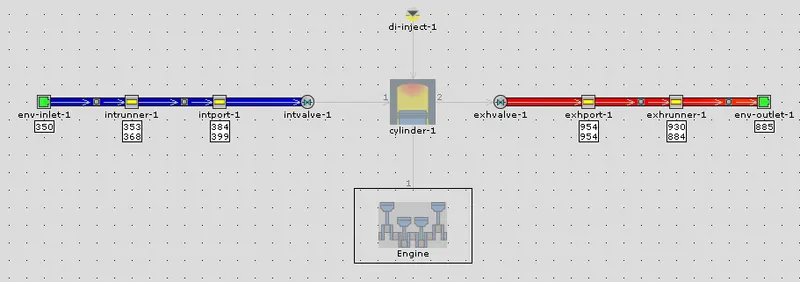
Single cylinder DI model is available in the GT-suite tutorial when opened we get the engine model as shown below,
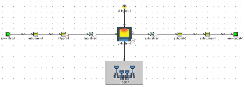
All the parts in the above engine model is explained below,
# env-inlet-1:
* This part represents the environment from where the intake air is drawn into the engine.
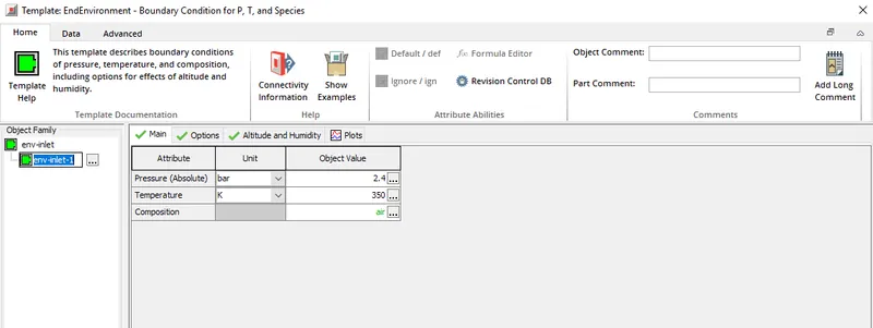
* Initial conditions of the air is defined here. Pressure is set to 2.4 bar and temperature is set to 350 K and the composition of the fluid taken into the cylinder is set to air.
* Under the options tab pressure flag is set to standard and reversion flow composition is set to imposed. Altitude and humidity attributes are ignored.
# intrunner-1:
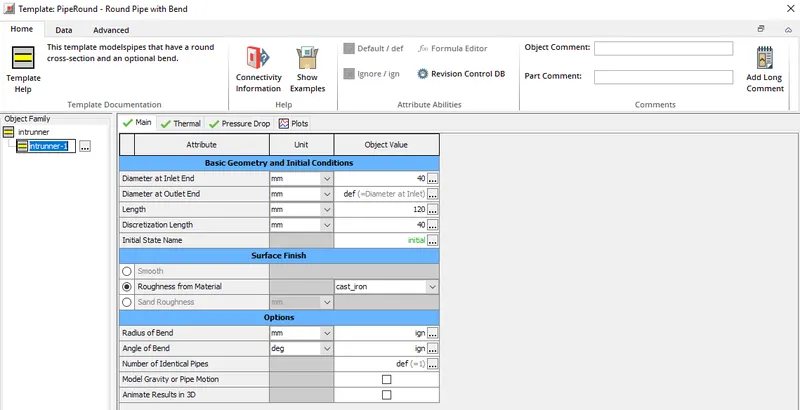
* This part represents the runner through which the intake air flows. Inlet and outlet diameter of the intake runner is set to 40 mm. Length of the intake runner is set to 120 mm with discretization length set to 40 mm.
* Discretizaton length helps in computing the `Deltat` when explicit solver is used.
* Material of the intake runner is set to cast iron.
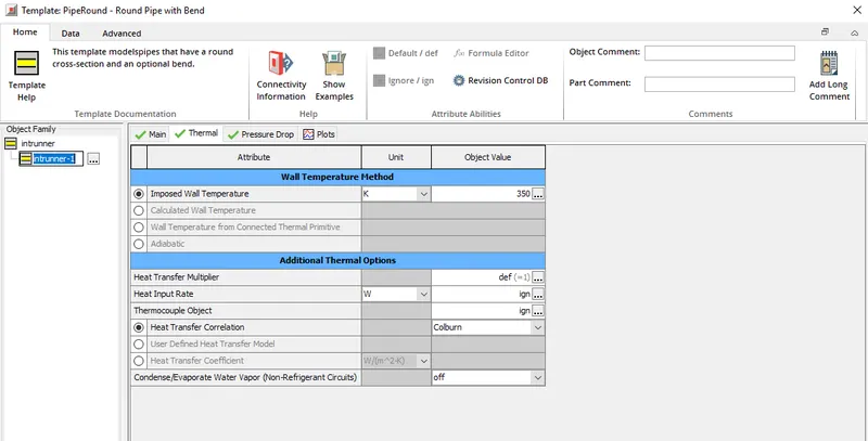
* Under the thermal tab the imposed wall temperature is set to 350 K, this imposed temperature is used to calculate the heat transfer between the fluid and the walls of the intake runner.
* Heat transfer corelation is set to colburn, this model computes the heat transfer coefficient.
* Apart from the above mentioned tab all other attributes are ignored.
* Since pressure drop along the intake runner is not considered all the attributes under the pressure tab is ignored.
# intport-1:
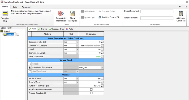
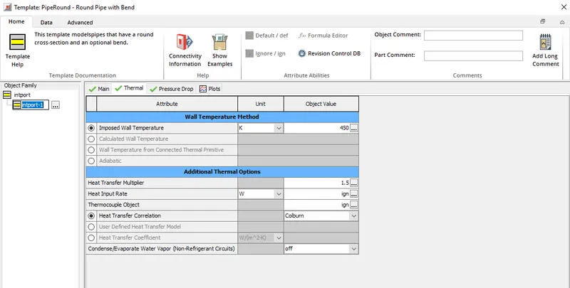
* This part represents the intake port, the inlet diameter and outlet diameter of the intake port is set to 40 mm. Length of the intake port is set to 80 mm along with the discretization length of 40 mm.
* Material of the intake port is set to cast iron.
* Imposed wall temperature is set to 450 K and the heat transfer corelation is set to colburn.
* Since no pressure drop along the intake port is considered all th attributes under the pressure tab are ignored.
# intvalve-1:
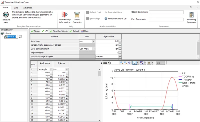
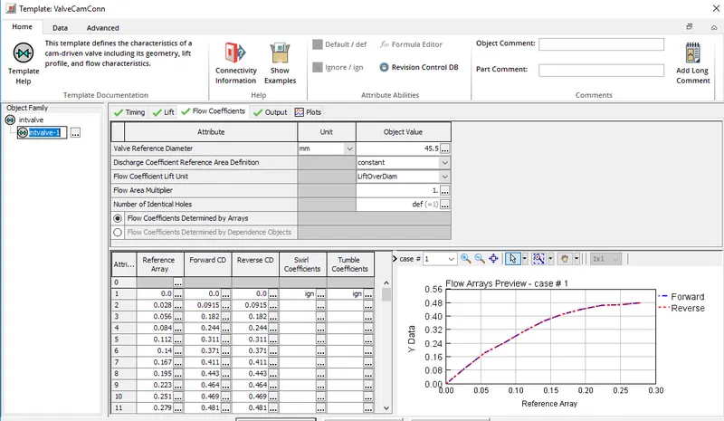
* This is defined as a connection which connects the intport-1 to the combustion chamber.
* Cam timing angle is defined to 239 degree.
* The valve lift profile is set in the lift tab.
* Also the flow coefficients are also set.
# cylinder-1:
* This part represnts the combustion chamber first comes the main tab under which first attribute is initial state object for which the object value is set as initial.
* Initial object value has the attributes required to define the initial conditions for the intake air. As set in the env-inlet-1 pressure is set to 2.4 bar and temperature is set to 350 K and the intake charge composition is set to air.
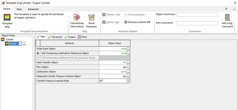
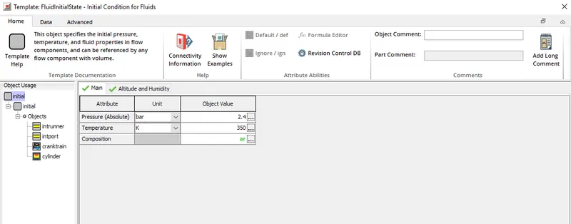
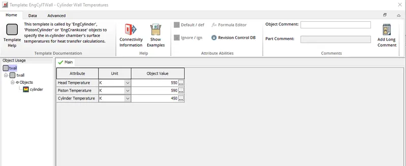
* Second attribute under the main tab is wall temperature defined by the reference object for which the object value twall is set. This object value defines the initial temperature of head temperature, piston temperature and cylinder temperature. Below snip shows the different values set for these parameters,
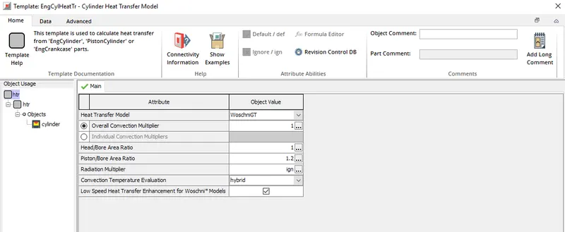
* Third attribute under main tab is heat transfer object for which the object value is set to htr, under this object value the heat transfer model which computes the incylinder heat tranfer is defined for this simuation WoschniGT is selected.
* Head to bore area ratio is set a value of 1 and piston to bore area ratio is set to 1.2.
* Next attribute is combustion object for which comb object value is set.
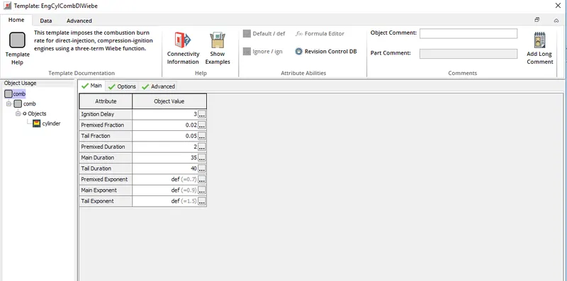
* This object value defines different parameters concerned with the combustion of diesel such as ignition delay, premixed fraction, tail fraction etc.
* Ignition delay of 3 degrees is set. As we know at the end of compression stroke diesel fuel is injected into the combustion chamber but as soon as the diesel fuel is injected it does not combust there is small delay from injection of the diesel fuel to start of combustion which is called as ignition delay. Ignition delay is measured in terms of crank angles.
* Premixed fraction for this model is set to 0.02. To understand this parameter we need to understand how combustion takes place inside a diesel engine.
* Combustion takes place in three different phases. In the first stage rate of burning is very high and hence there is a rapid increase in pressure and this lasts for only few crank angles. Second stage is called the main stage where there is a gradual decrease in heat release rate and heat release in this stage lasts for about 40 degree crank angles. About 80% of the fuel energy is released in this two stages and last is the tail end where around 20% of the fuel energy is released and there is a distinguishable heat release.
* Above mentioned premixed fraction corresponds to the fraction of fuel that is burnt in the first stage of combustion. As mentioned above the initial stage in which there is a steep pressure rise, this stage lasts for few crank angles and this duration if set to 2 degree.
* Tail fraction is set to 0.05 and the corresponding duration is set to 40 degree crank angle.
* Main duartion of the combustion is set to 35 degree crank angle.
* Apart from the above mentioned attributes there are premixed, tail and main exponent for which default values are set.
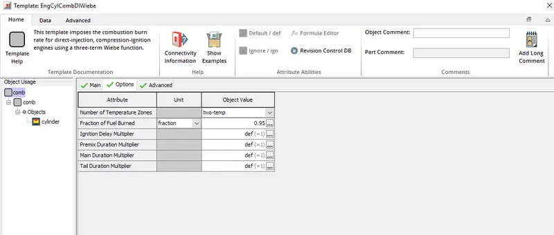
* Next comes the option tab under the comb object value and first attribute under the comb object value is number of temperature zone which is set to 2.
* fraction of fuel burned is set to 1.
* Apart from this there are certain multipliers such as ignition delay multiplier, premix duration multilier, tail end multiplier, main duration multiplier all these are set to default value of 1.
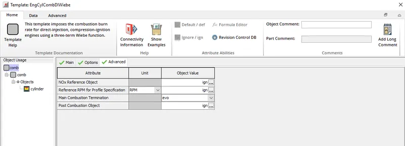
* Next tab under the comb object value is advanced tab, attributes here correspond to `No_x` reference object which is ignored.
* Attribute Main combustion termination is set EVO. apart from this other attributes under this tab is ignored.
* All the above stated attributes comes under main tab, there are other tab such as advanced and output all the attributes are ignored.
# di-inject-1:
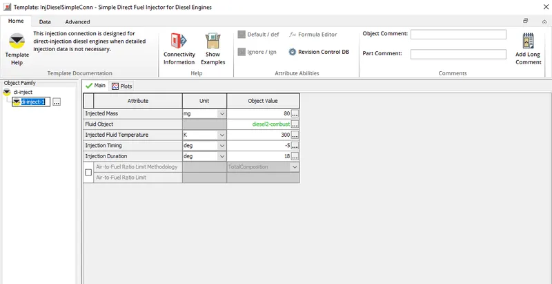
* This is defined as a connection in the engine model and this part represents the injector which injects diesel into the combuston chamber.
* First attribute is injected mass which is set to 80 mg i.e for each cycle 80 g of fuel is injected into the combustion chamber.
* Fluid object is defined as diesel-2-combust.
* Injected fluid temperature is set to 300 K.
* Injection of diesel into the combustion chamber is set at 5 degree before TDC.
* Injection duration is set to 18 degree.
# Engine:
* Under the main tab engine type is set to 4 stroke.
* Speed and load specification is set to speed. Engine speed is given as parameter, simulation is run for two different speeds viz 1800 rpm and 3600 rpm.
* For engine friction object attribute the object value is set as friction. The set object value friction has certain attributes such as constant part of FMEP 0.4.
* Peak cylinder pressure factor is set to 0.005.
* Mean piston speed factor is set to 0.09 bar/(m/s).
* Mean piston speed squared factor is set to 9e-4 bar/(m/s)^2.
* Start of cycle is set to -95 degree.
* Cylinder geometry is defined under the cylinder geometry tab.
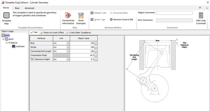
* Since there is only one cylinder the firing order is defined to the cylinder as 1.
# exhvalve-1:
* All the attributes concerned with this connection is same as that of intvalve-1.
* Lift profile and flow coefficients defined for this valve is same as that of intvalve-1.
# exhport-1:
* This part is same as that of intport-1 and this serves as channel through which exhaust gases are vented out.
* Inlet and outlet diameter is set to 30 mm along with a length of 60 mm and discretization length of 55 mm.
* Material of the export-1 is set to cast iron.
* Imposed wall temperature is set to 550 K, this set temperature is used to compute the heat transfer between the fluid and the wall.
* Heat transfer coefficient is computed using the colburn model.
* No pressure drop is considered when the flow takes place and hence all the attributes in the prssure tab is ignored.
# exhrunner-1:
* Inlet and outlet diameter is set to 30 mm along with a length of 150 mm and discretization length of 55 mm.
* Material of the exhrunner is set to steel.
* Imposed wall temperature is set to 600 K and the heat transfer corelation is set to colburn.
* As far as pressure drop across the exhrunner-1 is concerned it is ignored and hence all the attributes under the pressure tab is set to ign.
# env-outlet-1:
* This represents the environment into which the exhaust gases are vented out.
* Pressure is set to 2.4 baralong with a temperature of 350 K.
# Simulations:
* Simulation is run at two different speed's viz at 1800 rpm and 3600 rpm and the engine performance parameters are noted and it is compared with that of SI engine.
-> Engine performance parameters of DI engine:
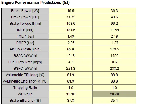
* From the above result it can be observed that as speed is increased the power o/p increases.
* As far as BSFC is concerned even it has increased from 221.3 g/kW-h to 238.2 g/kW-h.
* A/F ratio also gets increased.
* Temperature contour:
-> Engine performance parameters of SI engine:
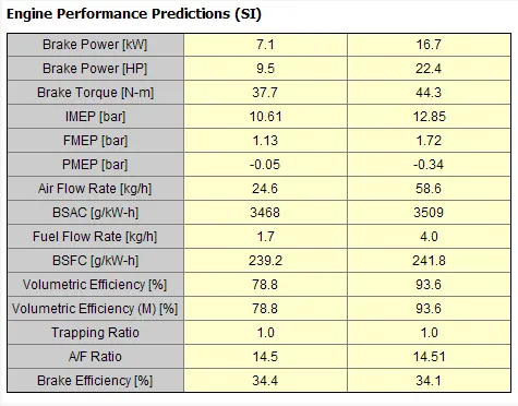
* Above shown engine performance predictions are obtained by running simulation on single cylinder SI engine for two different speeds viz 1800 rpm and 3600 rpm.
* Comparing power o/p from SI and DI engine it is clear that at a given speed DI engine produces more power. Highercompression ratio of the DI engine is the reason for higher power o/p from DI engines.
* Comparing the BSFC, for SI engine it is high and for DI engine it is low which means for any given cycle in DI engine less fuel is consumed.
* Overall DI engine is better as far as engine performance is concerned but this comes with a cost aftertreatment devices since DI engine produce more pollutants compared to SI engines.
-> To make changes in MFB and note the changes in performance parameters:
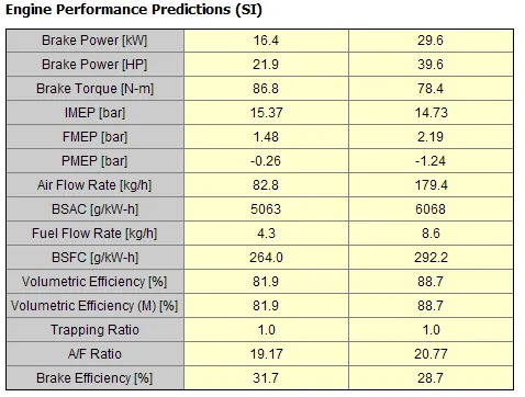
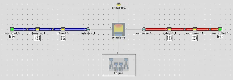
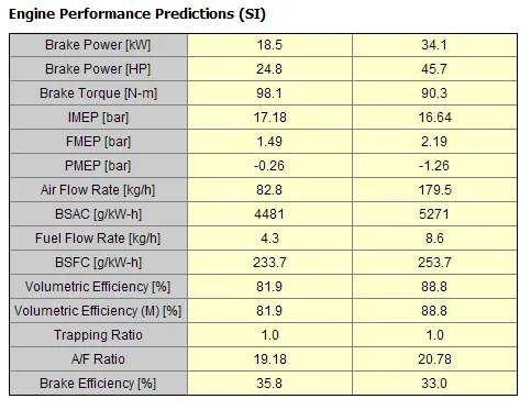
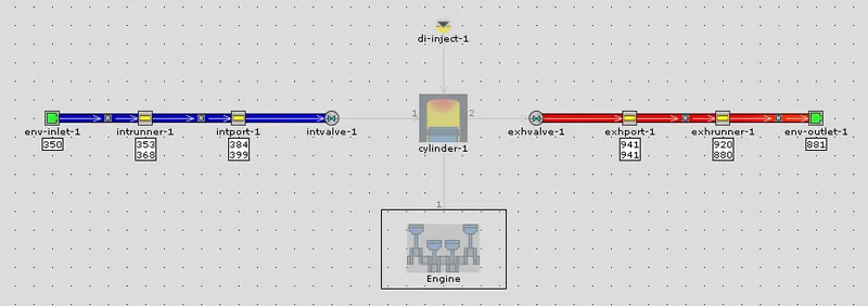
MFB refers to mass fraction burned and this attribute is concerned with cylinder-1 part. This attribute defines the fraction of fuel burned in each cycle, above shown performance predictions are computed at MFB set to 1. MFB is changed from the set value of 1 and changes in the engine performance parameters are observed,
* At MFB = 0.85:
* Temperature contour at MFB = 0.85:
* At MFB = 0.95:
* Temperature contour at MFB = 0.95:
* It is observed that as MFB is reduced the performance parameters such as power o/p gets reduced.
* BSFC gets increased as we reduce the MFB.
* Observing the temperature contour and that too the exhaust temperature it is observed that as MFB is reduced from 1 to 0.85 the there is distinguishable reduction in the exhaust tempertaure