Week - 4
1. Implement control logic of a “washing machine” using Stateflow as per given sequence:
- If the power supply is available, the system gets activated
- If the Water supply is not available, stop the process & indicate through LED
- Soaking time should be 200s followed by Washing time of 100s.
- Then rinsing happens for next 20s & dryer runs for 50s
The control logic for the washing machine is developed using the stateflow. The inputs for the logic includes the power supply for the activation of the system followed by the input of water supply. Once these two inputs are given, the washing process happens in a sequence : Soaking - Washing - Rinsing - Drying.
First the water supply and power supply is checked, if both are available, then the process begins. The indication for each of these supplies is given by the Lamp block. Each operation is considered to be one state in stateflow. The transition between the states is temporal based, as described below.
Soaking for 200 seconds
Washing for 100 seconds
Rinsing for 20 seconds.
Drying for 50 seconds.
Once this cycle is complete the process terminates and the finished Lamp block is green indicating that the process is complete. The sampling time is kept as 1 seconds. The simulink block is as follows :
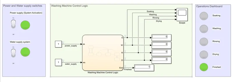
The stateflow logic is constructed as follows :
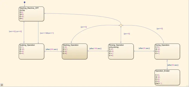
The initial state is default state when the washing machine is OFF. In this case, no operation happens. When the power supply and water supply is given, the condition is met, the transition from the default state to the Soaking operation state happens. After 200 seconds, the transition from this to the Washing operation state happens. Then after 100 seconds, the transition to the Rinsing operation state occurs, then after 20 seconds transition to the drying state happens. Finally, after more 50 seconds, the transition occurs to the End state, at which point the washing operations are all complete. At any state if the power supply is OFF, there will be a transition to the default OFF state. Likewise, if water supply is not there during the soaking operation, the state transition occurs towards the default OFF condition.
The simulink block is simulated for various test cases and the results are plotted as follows is shown below.
Case 1 : When power supply is OFF, Water supply is OFF. As both the inputs are in OFF condition, no washing occurs.
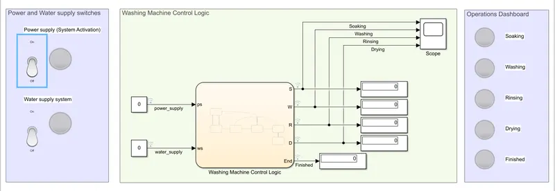
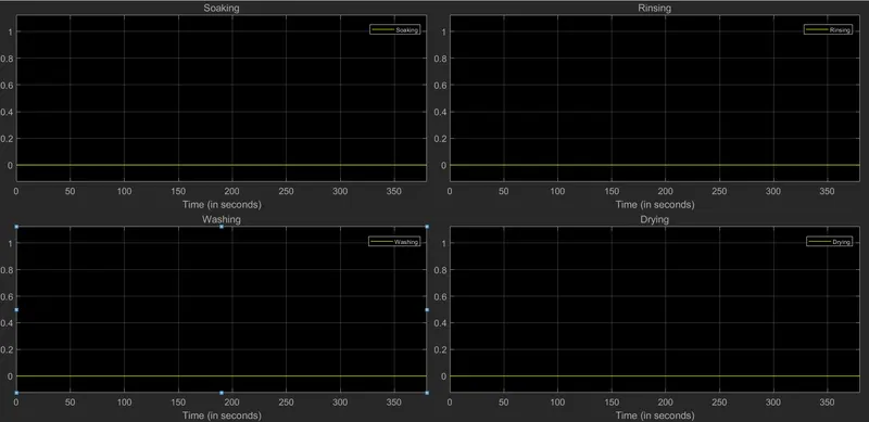
As it can be noticed, the operation doesnt happen through the simulation, as the input conditions are not met.
Case 2 : When power supply is OFF, Water supply is ON. Since, the power supply is OFF, the washing process doesnt occur.
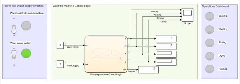
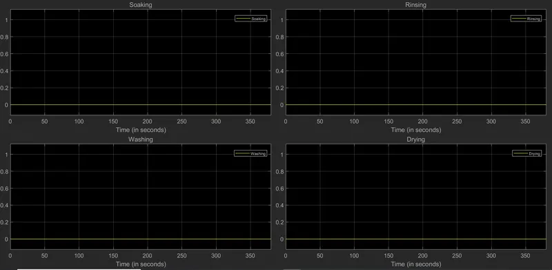
Since both the input conditions are not met, the washing operation doesnt happen throughout the entire simulation.
Case 3 : When power supply is ON, Water supply is OFF. Since the water supply is OFF, the washing process doesnt occur.

Similar to the previous two cases, the input conditions are not met, the washing operation doesnt happen throughout the entire simulation.
Case 4 : When power supply is ON, Water supply is ON. Since both the input conditions are met, the washing process starts and proceeds one step after another based on the time constraints given for each operation.
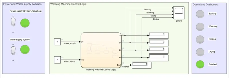
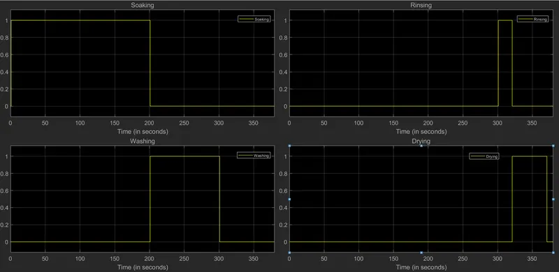
The dashboard created indicates the current operation going in the washing machine.
2. Make a Simulink chart for the “Gear shift” logic as per below conditions:
Speed Range(kmph) Gear
0 to 15 1
16 to 25 2
26 to 40 3
41 to 60 4
Above 61 5
Give speed input while the simulation is running & display the gear number.
The simulink block is as follows :
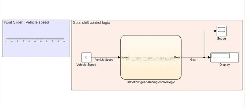
The stateflow diagram indicating the control logic is as follows :
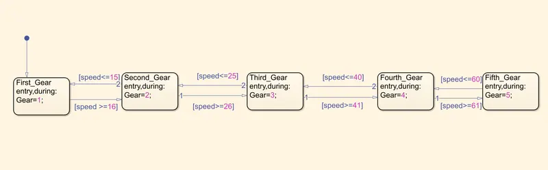
The transition between the different gears is dependent on the speed conditions given above.
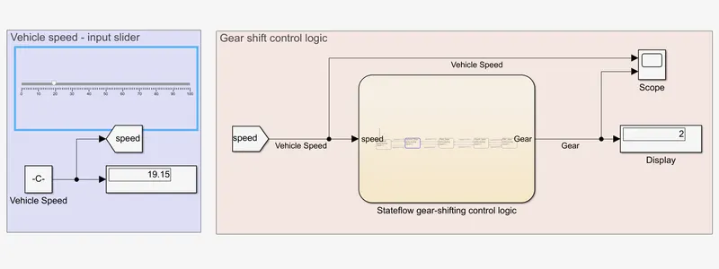
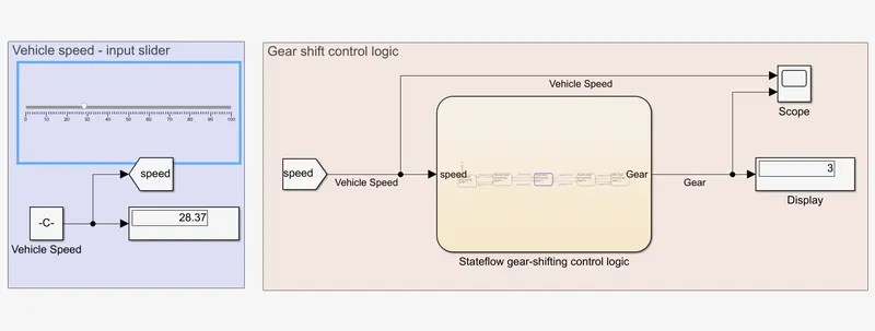
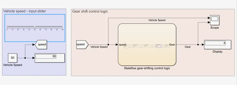
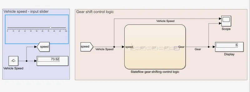
The speed is varied while simulation, and the gear number is plotted. The simulation results at different instances during the simulation is shown below.
Case 1 : When speed is between 0kmph and 15kmph. The gear number at the display is 1.
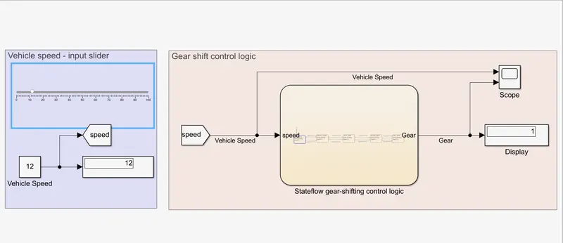
Case 2 : When speed is between 16kmph and 25kmph. The gear number at the display is 2.
Case 3 : When speed is between 26kmph and 40kmph. The gear number at the display is 3.
Case 4 : When speed is between 41kmph and 60kmph. The gear number at the display is 4.
Case 5 : When speed is above 61kmph. The gear number at the display is 5.
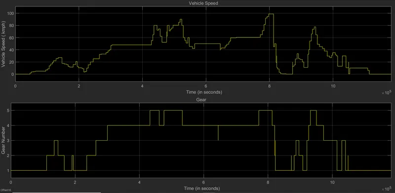
The input velocity plot and the corresponding gear numbers for the entire simulation is plotted below :