Week - 4
CONTROL LOGIC FOR A WASHING MACHINE AND A GEAR SHIFT:
OBJECTIVE:
- To Implement control logic of a “washing machine” using Stateflow as per given sequence:
- If the power supply is available, the system gets activated
- If the Water supply is not available, stop the process & indicate through the LED.
- Soaking time should be 200s followed by Washing time of 100s.
- Then rinsing happens for the next 20s & the dryer runs for the 50s.
- After all the processes have completed turn on the finished LED.
2.To Make a Simulink chart for the “Gear shift” logic as per the below conditions:
Speed Range(kmph) Gear
0 to 15 1
16 to 25 2
26 to 40 3
41 to 60 4
Above 61 5
Give speed input while the simulation is running & display the gear number.
PROCEDURE:
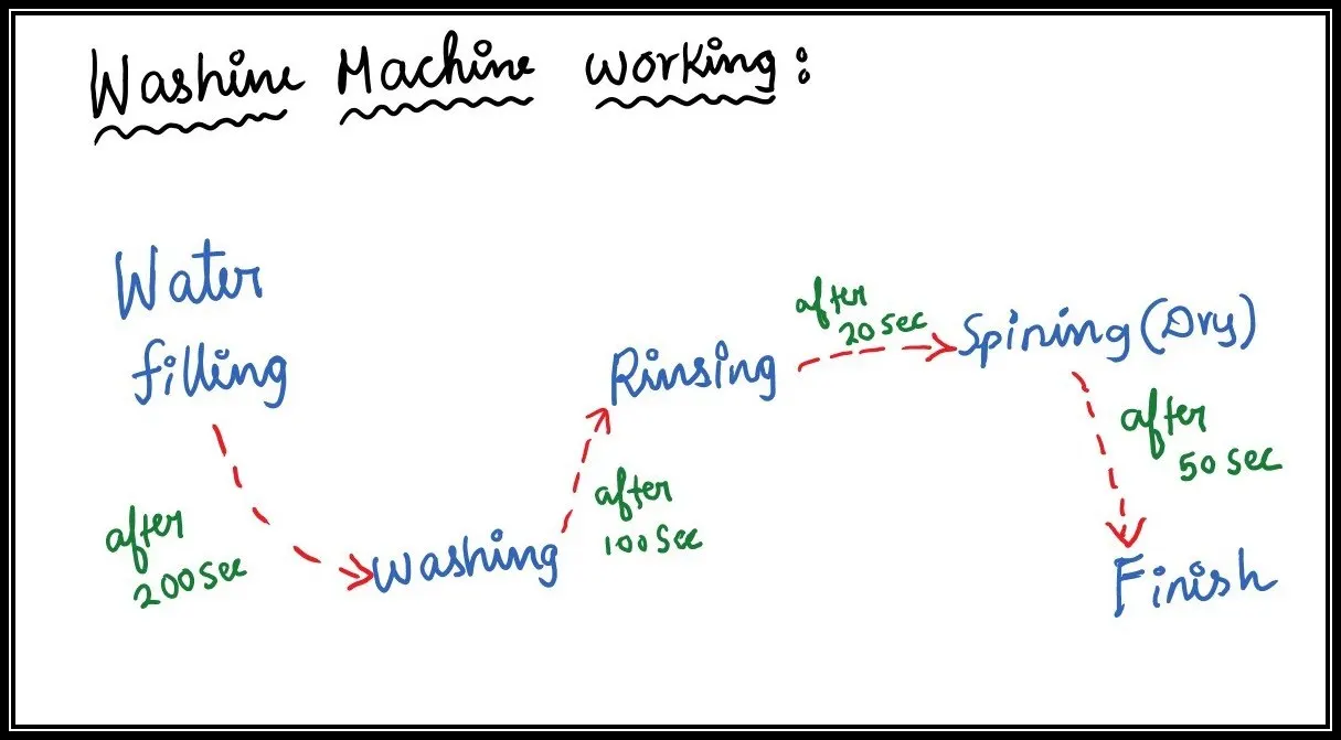
- The above diagram is the overall idea about the working of a washing machine.
- In the first step, the water filling will occur.
- Then, after some period of time delay, it moves to the next step.
- After the water filling completes, the washing process will take place.
- Then with a period of time delay, it moves to another step.
- Then, the rinsing process will take place.
- Then, the spinning process will occur for a period of time, and washing the overall process completes.
STEPS FOLLOWED IN CONTROL CHART:
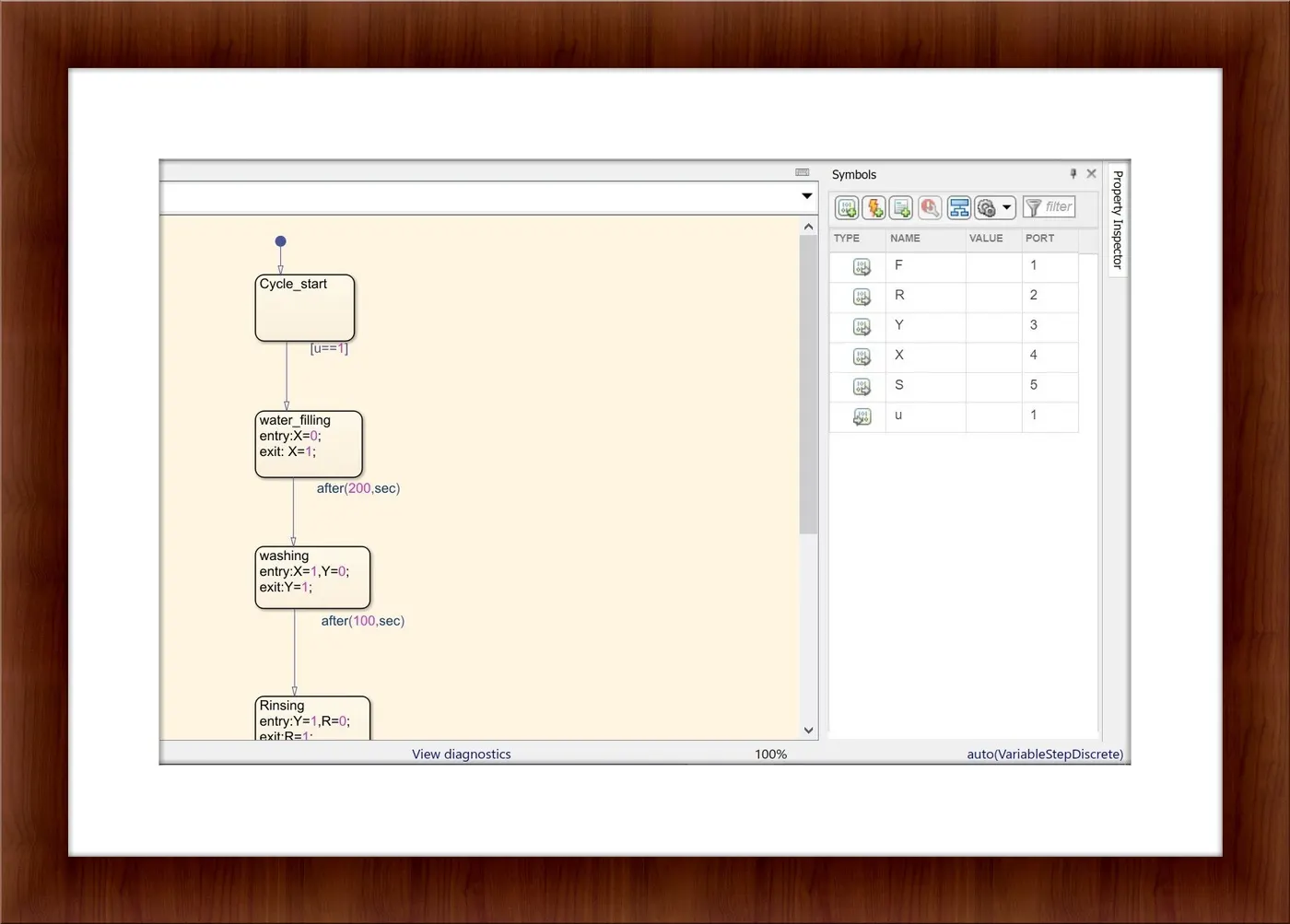
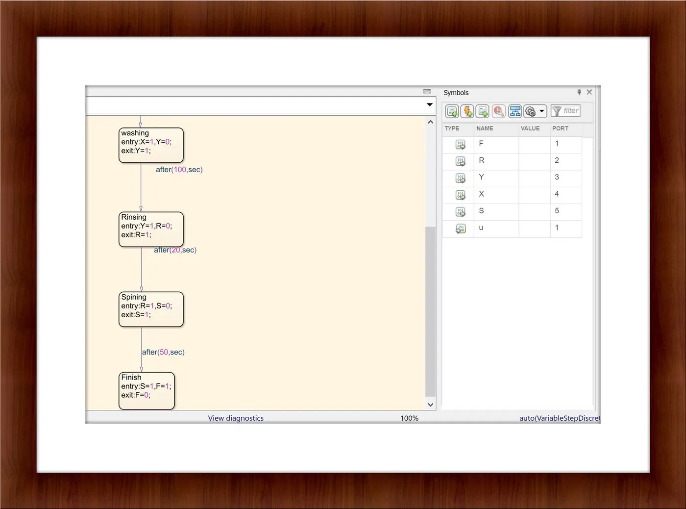
- In the Simulink model, a chart is taken and in the chart, several state flows with the conditions are declared.
- In the chart, the initial state flow is mentioned as the cycle start block with the condition declared U=1.
- The condition of U will be declared outside the chart and it is the input for the chart and it will explain in the further step.
- If the condition of U satisfies, then it will proceed to the next step.
- In the next flow, Water filling is done with the inputs and exit conditions are declared.
- The initial condition for the water filling is X=0 and the exit condition X=1.
- Then it will proceed to the next step with the time delay of 200 seconds as it is mentioned near the arrow mark.
- In the next step, the washing process will occur.
- The input and the exit condition for the washing process are X=1, Y=0, and Y=1.
- Then it will proceed to the next step with the time delay of 100 seconds as it is mentioned near the arrow mark.
- Then in the next state flow, the rinsing process will start with the entry and the exit condition as Y=1, R=0, and R=1.
- Then it will proceed to the next flow with a time delay of 20 seconds.
- In the state flow, the spinning process will take place with the initial condition and exit condition as R=1, S=0, and S=1.
- Then it moves to the next state, Finish with a time delay of 50 seconds.
- Then after entering these values in the Stateflow, open the symbols pane and in that declare all the variables as mentioned in the different states.
- The U is the only input variable and the remaining all variables mentioned in the different states are declared as output variables.
- After completing the above steps, the input variable U is declared outside and the outputs are to be displayed and after finishing the entire washing process the finish LED lamp will need to glow.
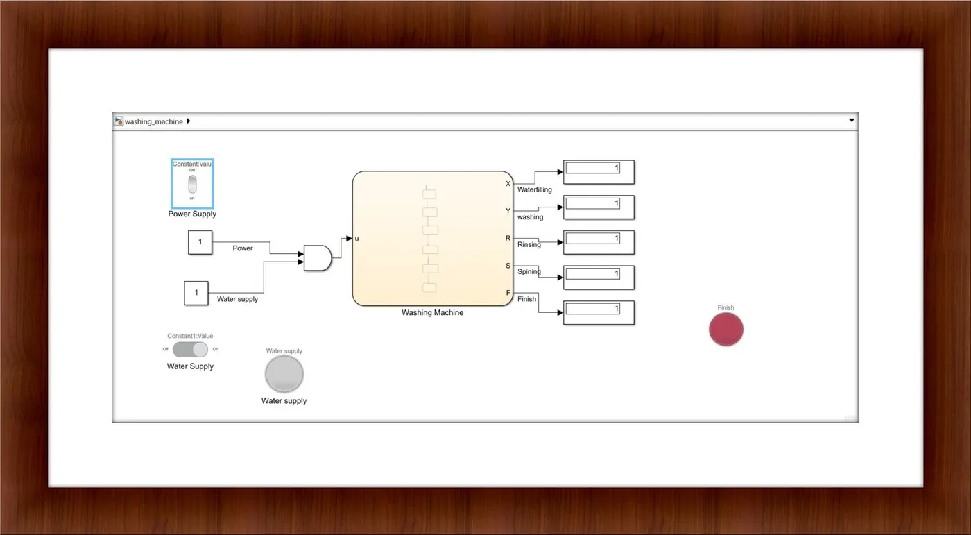
- In the Simulink library browser, the rocker switch is taken and it used to display the power supply conditions.
- The rocker switch is connected to the constant block in order to view the conditions on and of the switch.
- If the switch is in off condition, in the constant block 0 will be displayed and if it is in on condition, the 1 will display in the constant block.
- Then, again in the library browser, the slider switch is taken for the water supply.
- Similarly as mentioned above, the rocker switch is also connected to the constant block, and based on the condition on or off, the value will be displayed as 0 or 1.
- Then a lamp is taken from the library browser and as mentioned in the question, it will glow if the water supply is in off condition.
- If both the conditions satisfy only the washing machine will operate otherwise the process won't start.
- So AND block is used and these two conditions(ie the power supply and water supply) are given as input.
- If both the condition satisfies only the output from the and block will be 1 (ie U=1) and so it moves to the different states as mentioned above.
- Since the variables in each state are declared as output, the outport port will be generated and it is connected to the display block.
- Based on the condition given if the washing process is done the finish led will need to turn on.
- So a lamp is taken from the library browser and it connected to the finish block.
- After entering all the steps the time is set in the run as 600 seconds and the simulation is run using the run command in order the view the process flow through the different states as declared.
RESULTS:
- The various conditions are checked by switching the power supply off, water supply off and both conditions on and off are checked and it works perfectly.
- The output for various conditions are discussed below:
1)The power supply and the water supply is in on condition:
- Since both the condition is in on condition, the washing process is done and so the finish lamp will glow and all the displays will be shown 1 constant value indicates that all process is carried out.
2)The power supply is off and the water supply is in on condition:
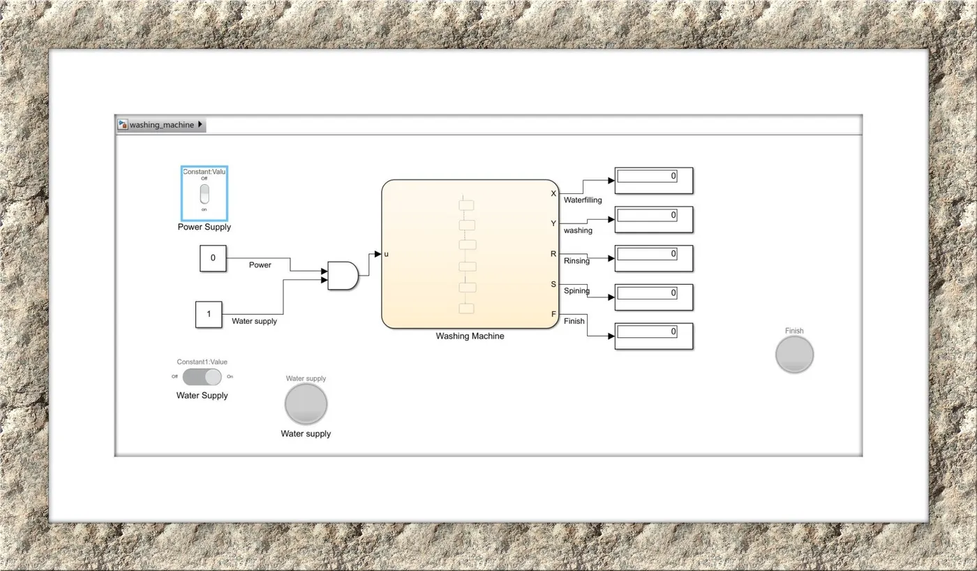
- Since the power supply is no in on condition the washing process is not carried out and so the finish lamp will also not glow. Since the water supply is in on condition the water supply lamp will not glow and all the display will be shown as 0.
3)The power supply is in on condition and the water supply is in off:
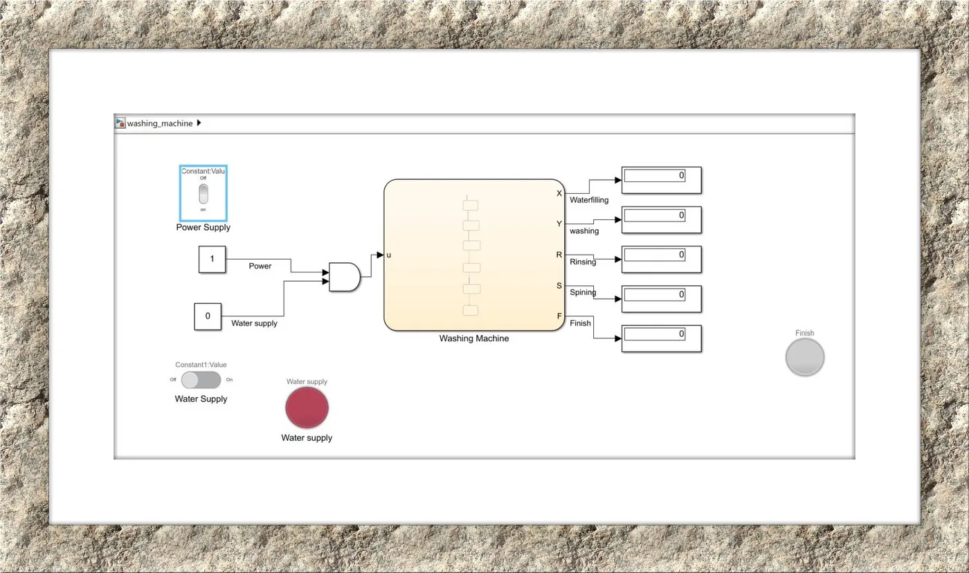
- Since the water supply is in off condition, the water supply lamp will glow and due to the input condition fails the washing process won't start and the finish lamp will not glow and all the display will be shown as 0.
4)Both the power supply and water supply is in off condition:
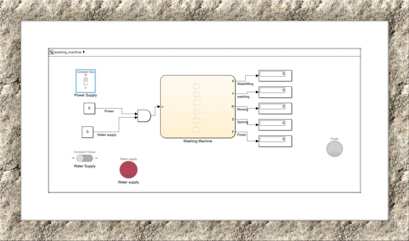
- Since both conditions fail, the washing process won't start and the water supply lamp will glow and all the outputs are 0.
2)SIMULINK CHART FOR THE GEAR SHIFT:
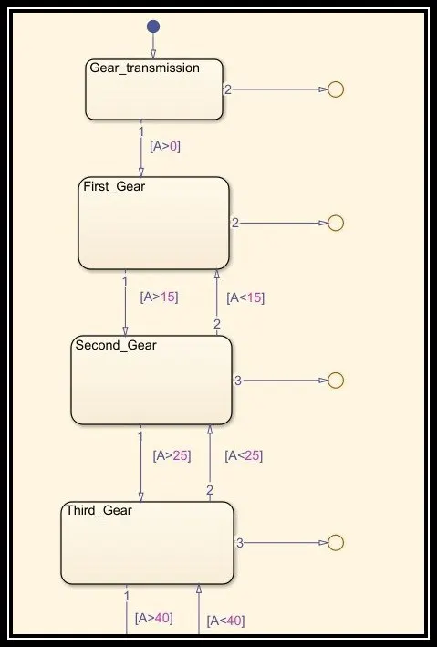
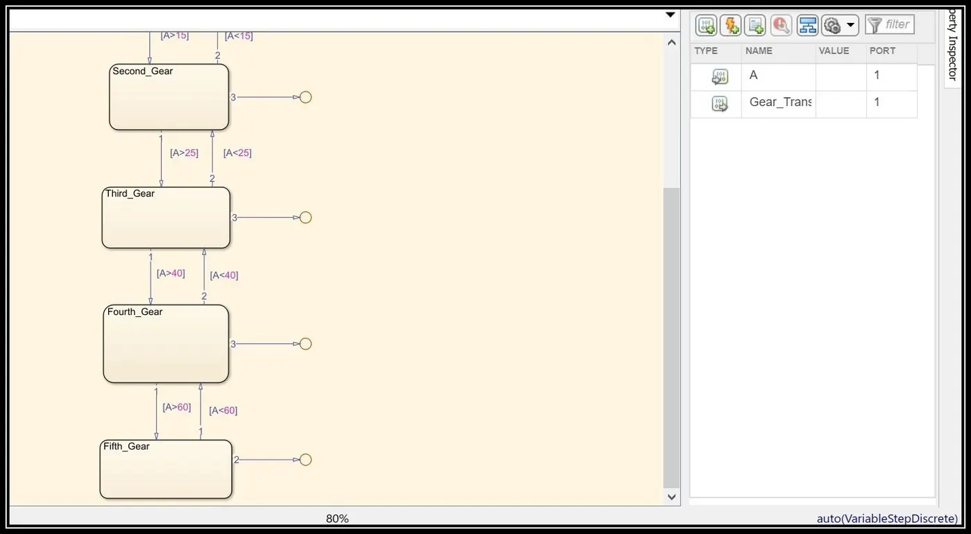
- The Initial state flow block is displayed with gear transmission name and it proceeds to the next flow if the condition satisfies A>0 (ie when the acceleration starts).
- The idea is simple and it is in accordance with the speed, it moves to higher gears when acceleration increases and it must be lowered when the acceleration reduces.
- Based on the speed range, the corresponding gear has to be selected and the condition is set to satisfy this.
- For the first gear, the speed range has to be A>0Kmph and A<15Kmph.
- If the speed range is within the above limit, the vehicle will be in the first gear.
- For the second gear, the speed range is A>15Kmph, A<25Kmph.
- Similarly, if the vehicle is in the above limit it will be in the second gear.
- For the third gear, the speed range is A>25Kmph, A<40Kmph.
- If the vehicle is in the above limit, the vehicle is in the third gear.
- For the fourth gear, the speed range is A>40Kmph, A<60Kmph.
- If the vehicle is in the above limit the vehicle will be in the fourth gear.
- For the fifth gear, the speed range is A>60Kmph.
- If the vehicle accelerates above 60Kmph, it will be in fifth gear.
- After completing these states, select the add output port in the prepare tab and connect it to each gear state flow block in order to view the output.
- Then, select the symbols pane in the prepare tab and declare input variable A and gear transmission mode as the output variable.
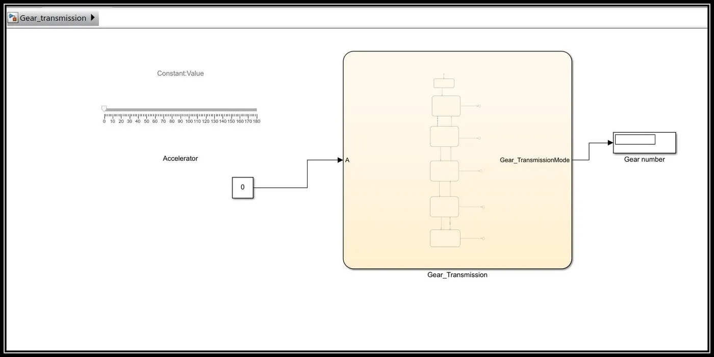
- Since the acceleration has to be given in simulation time, a slider is used in order to give the input to the control chart.
- Based on the given acceleration, the vehicle will be in the appropriate gear and the corresponding gear will be displayed in the display block.
RESULTS:
- Since the input is given in real-time the run time set as infinity and run the simulation.
- The acceleration is given using the slider block by sliding left and right and based on the given speed the appropriate gear will be displayed in the display block
First Gear:
Range: A>0, A<15
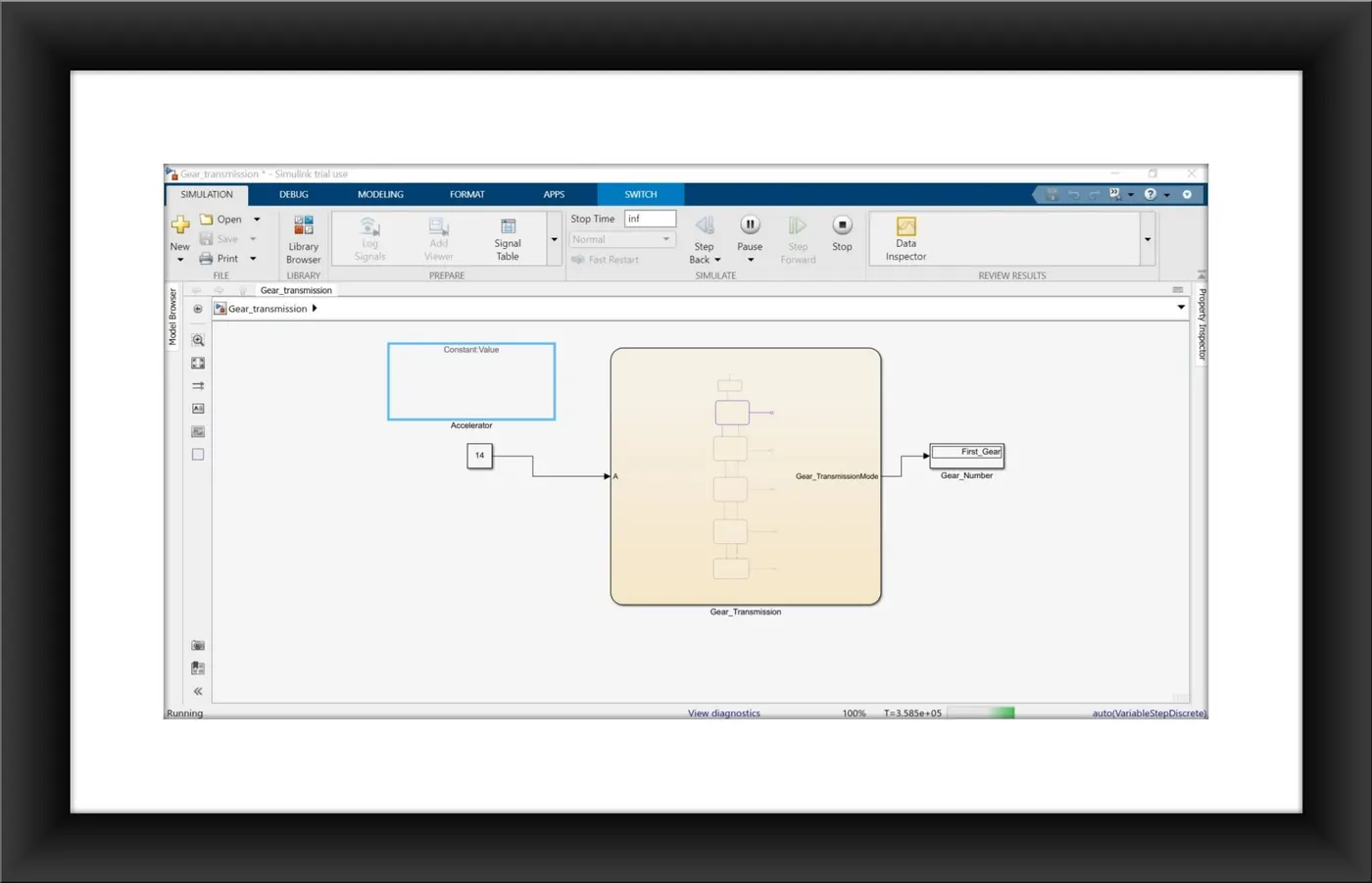
- By sliding the slider and the acceleration is given as 14Kmph and so the corresponding gear number is displayed in the display block.
Second Gear:
Range:A>15,A<25
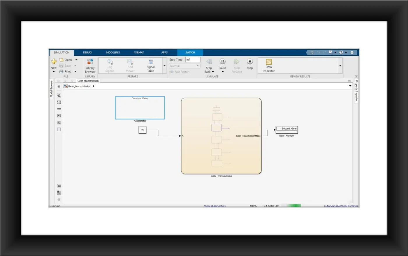
- Since the acceleration is given as 16Kmph the Second gear is displayed in the display block.
Third Gear:
Range:A>25,A<40.
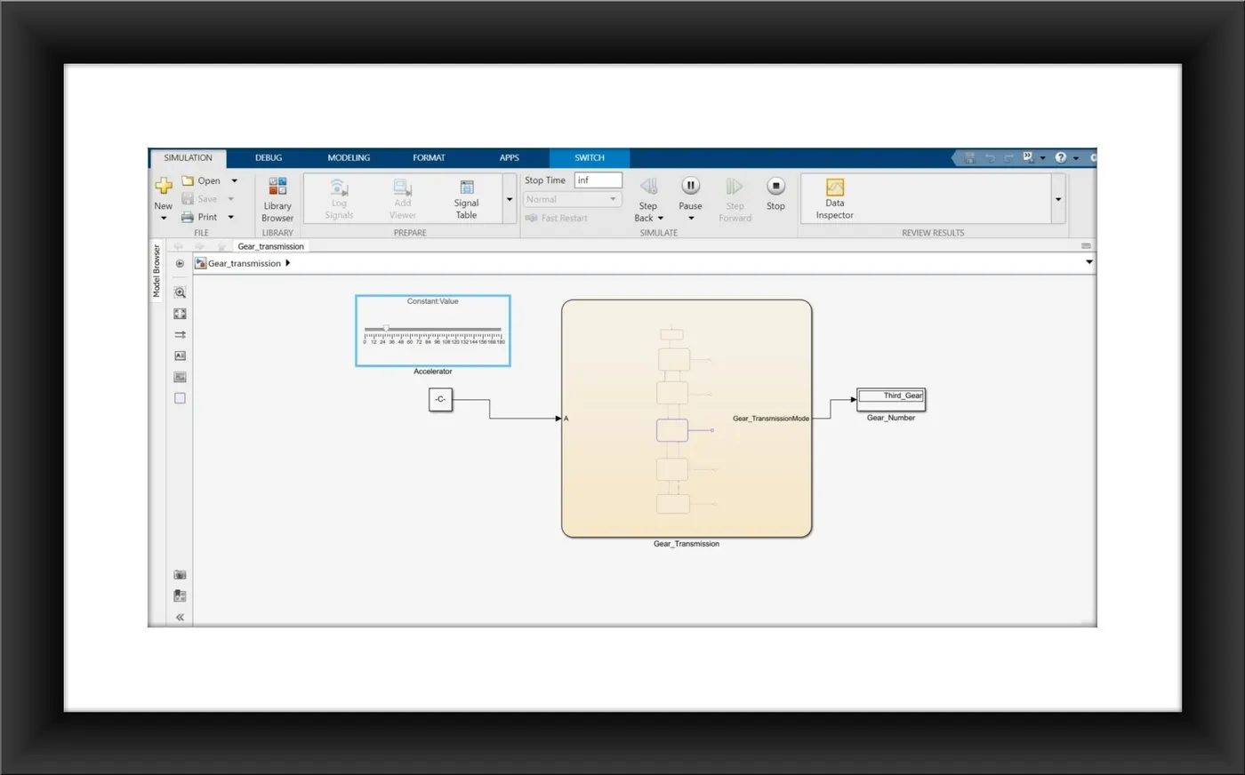
- Since the acceleration is given as 27Kmph the gear number display as gear number 3.
Fourth Gear:
Range:A>40,A<60.
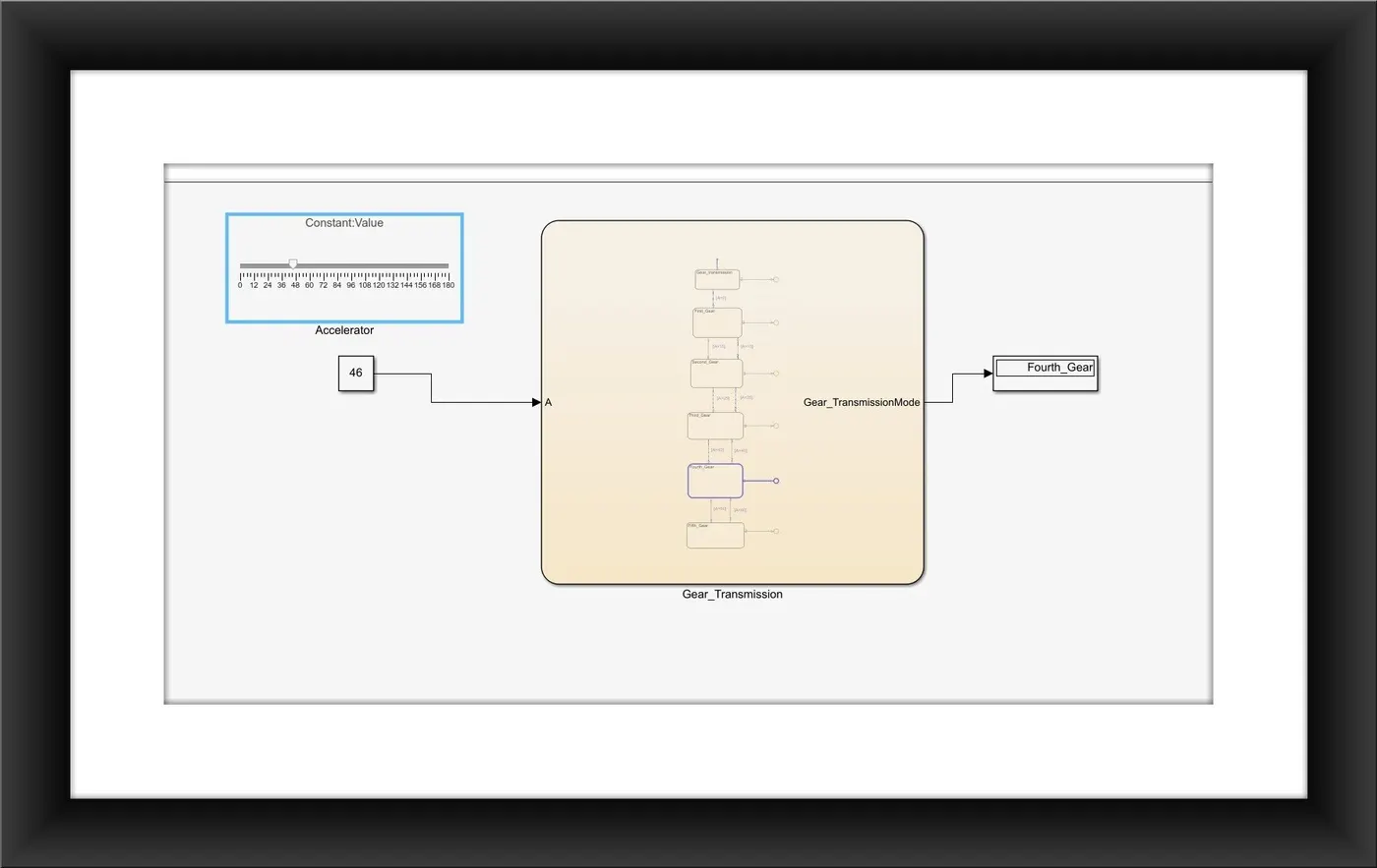
- Since the acceleration is given as 50Kmph, the gear number displays as 4.
Fifth Gear:
Range: A>60.
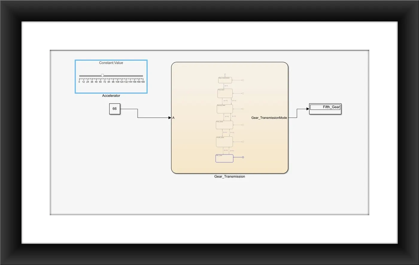
- Since the acceleration is given as 64, the gear number displays as fifth.
LEARNING OUTCOMES:
- How to define different Stateflow according to the conditions.
- How to simulate the model in real-time with varying inputs.