Week - 4
1ST QUESTION
- Implement control logic of a “washing machine” using State flow as per given sequence:
- If the power supply is available, the system gets activated
- If the Water supply is not available, stop the process & indicate through LED
- Soaking time should be 200s followed by washing time of 100s.
- Then rinsing happens for next 20s & dryer runs for 50s
After all the processes have completed turn on the finished LED
Solution:
Working Principle of Washing Machine:
The main principles behind the working of a washing machine are the centrifugal and centripetal forces, where centrifugation helps quicken the process of sedimentation of different density particles to clean the laundry in the washing machine.
The washing machine operates in two primary cycles. These are the wash cycle and the rinse cycle.
- The wash cycle involves the principle of centrifugal force. This force’s direction is from inside to outside, which makes sure that every part of the cloth is rinsed adequately in the soap water mixed in the machine.
- The rinse cycle involves the principle of centripetal force. This force acts from outside to inside and creates a vacuum-like space in the middle of the washing machine.
These two cycles work one after another several times, and as a result, the entire cleaning process occurs.
Parts of Washing Machine:
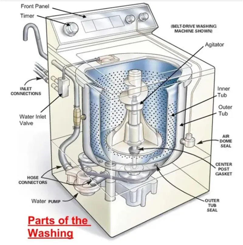
1) Water inlet control valve: Near the water inlet point of the washing machine there is water inlet control valve. When you load the clothes in washing machine, this valve gets opened automatically and it closes automatically depending on the total quantity of the water required. The water control valve is actually the solenoid valve.
2) Water pump: The water pump circulates water through the washing machine. It works in two directions, re-circulating the water during wash cycle and draining the water during the spin cycle.
3) Tub: There are two types of tubs in the washing washing machine: inner and outer. The clothes are loaded in the inner tub, where the clothes are washed, rinsed and dried. The inner tub has small holes for draining the water. The external tub covers the inner tub and supports it during various cycles of clothes washing.
4) Agitator or rotating disc: The agitator is located inside the tub of the washing machine. It is the important part of the washing machine that actually performs the cleaning operation of the clothes. During the wash cycle the agitator rotates continuously and produces strong rotating currents within the water due to which the clothes also rotate inside the tub. The rotation of the clothes within water containing the detergent enables the removal of the dirt particles from the fabric of the clothes. Thus the agitator produces most important function of rubbing the clothes with each other as well as with water. In some washing machines, instead of the long agitator, there is a disc that contains blades on its upper side. The rotation of the disc and the blades produce strong currents within the water and the rubbing of clothes that helps in removing the dirt from clothes.
5) Motor of the washing machine: The motor is coupled to the agitator or the disc and produces rotation. These are multispeed motors, whose speed can be changed as per the requirement. In the fully automatic washing machine the speed of the motor i.e. the agitator changes automatically as per the load on the washing machine.
6) Timer: The timer helps setting the wash time for the clothes manually. In the automatic mode the time is set automatically depending upon the number of clothes inside the washing machine and the type of wash cycle being performed.
7) Printed circuit board (PCB): The PCB comprises the various electronic components and circuits which are programmed to perform in unique ways depending on the load conditions (the condition and the amount of clothes loaded in the washing machine). They are sort of artificial intelligence devices that sense the various external conditions and make the decisions accordingly. These are also called fuzzy logic systems. Thus the PCB will calculate the total weight of the clothes, and find out the quantity of water and detergent required, and the total time required for washing the clothes. Then they will decide the time required for washing and rinsing.
8) Drain pipe: The drain pipe enables removing the dirty water from the washing that has been used for the washing purpose.
Simulink Model :
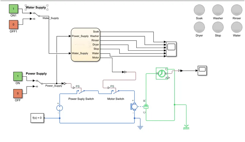
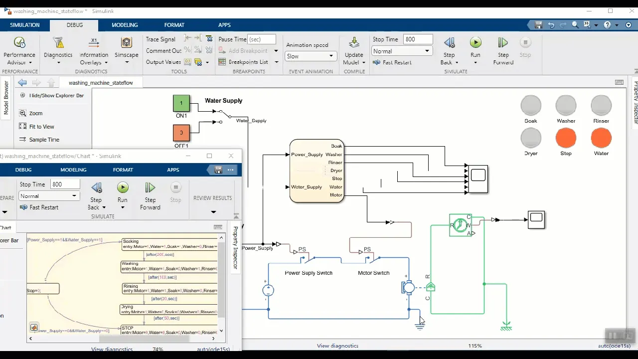
- Here water and power supplies are switched between 0 and 1 stage using manual switch.
- DC supply used to power Motor which is used inside washing Machine for rotation.
- For control logic chart is used.
Chart:
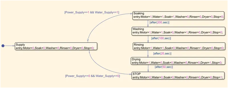
- Initially all indictors and motor are in closed/OFF state.
- When Power supply and water supply is available then soaking, washing, rinsing and drying taken place as per problem statement.
- In case Water supply or Power supply is not available then machine stops and indicates with red LED.
- If user wants to know about current state of washing machine, then he/she can check LEDs.
- Here Water LED indicates when user needs to switch ON (Green) or OFF (Red) water supply.
Results:
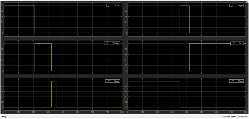
- Simulation runs for 800 secs.This graphs shows when and which process of Washing Machine is working and also tells that for how much time water is required and when Washing Machine is stopped.
2ND QUESTION:
- Make a Simulink chart for the “Gear shift” logic as per below conditions:
Speed Range (kmph) Gear
0 to 15 1
16 to 25 2
26 to 40 3
41 to 60 4
Above 61 5
Give speed input while the simulation is running & display the gear number.
Solution:
Transmission:
Transmission is used in cars to vary the torque going from the engine to the drive wheels. It is an important part of the drive train.
Cars require a transmission because their engine has a maximum RPM that it can spin at before damage occurs, known as redline (specifically, RPM is a measure of the rotating crankshaft). Second, every engine has a certain RPM at which it produces maximum horse power and torque In order to operate at a suitable RPM, a transmission makes use of gears; the gears vary how much torque and angular velocity is transmitted from the engine to the wheel, therefore allowing the RPM to remain below redline while also providing maximum horsepower.
FIGURE 1:
Operation:
Transmissions use what is called a gear ratio, which is a measure of the mechanical advantage their gears produce. The higher the gear ratio, the less angular velocity (meaning a lower RPM value) is being transmitted to the drive shaft, but this comes with a proportionally higher torque. A high gear ratio is desirable at low speeds, so that the wheels won't be spinning too fast while also getting enough torque to get the car moving. A low gear ratio is desirable to deliver maximum speed to the wheels, and therefore would be used at higher speeds when the wheels don't need as much torque.
PARTS:
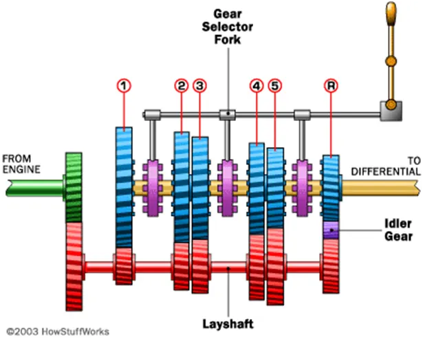
The transmission of a car has many working parts (clutch, layshaft etc.) but in principle are quite simple—use gears to vary how much torque gets to the wheels. Mentioned above was how this is done in terms of gear ratio, so below is a list of the working parts in a transmission and their role to accomplish this task. First, the input shaft (green part of Figure 3) coming from the engine will be spinning at the same speed as the engine. The first important part is what connects this to the transmission, and allows for the engine to run while the car is standing still.
- Clutch- The clutch is a major component of a manual transmission, and it is used often. Its purpose is to connect or disconnect the engine from the transmission. When disconnected, the engine will spin on its own and no power will be delivered to the wheels, which allows for gear changes, and for the car to run while not moving. When connected, the clutch connects the two systems and allows for power transfer and acceleration to occur.
- Layshaft- The layshaft (red) connects to the engine via the clutch, and spins as one unit. Therefore when the clutch is engaged, the layshaft will spin as long as the engine is running, and any change in engine speed will be relayed to the layshaft. It connects to the next part, which is what gets the car moving.
- Gears and output shaft- The gears (blue) and output shaft (yellow) are what connect to the drive shaft, differential, and finally the wheels. The shaft and gears do not spin as a single unit unless the purple part, known as the collar, is locked with a gear.
- Collar- This part is crucial for the main goal of the transmission, which is to get the wheels moving at the desired speed. If the collar isn't connected to a gear, as in Figure 3, the car is considered to be in "neutral", and the engine will provide no power to the wheels. It connects to the gear by its "dog teeth", and if you've ever heard a manual car grind during gear change it is these dog teeth attempting to lock into a gear. In modern cars, they use synchronizers to make the change of gears smoother.
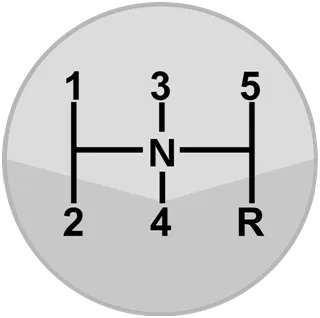
- Gear selector fork- This is what the driver uses to change the gears, seen in Figure 1. The moving of this fork changes the position of the collar, and allows the driver to change gears only when the clutch is disengaged. In Figure 3 it can be seen how a car goes in reverse, because the "idler gear" causes the reverse gear to spin in the opposite direction from the others.
Simulink Model:
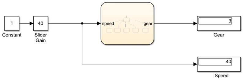
- Here speed is changed using Slider gain.
- Output i.e. gear number is shown using Display
- For control logic chart is used.
CHART:
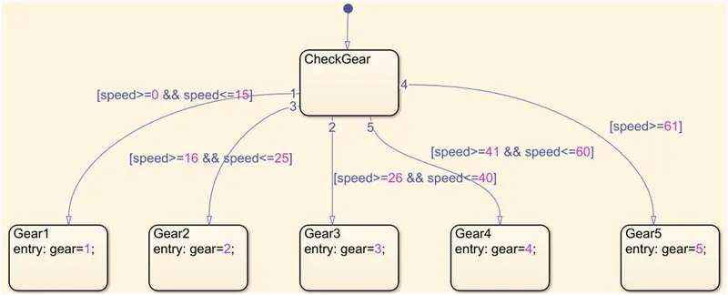
- According to problem statement, gear number is chosen as per the speed, where speed is input and gear is output.
RESULT:
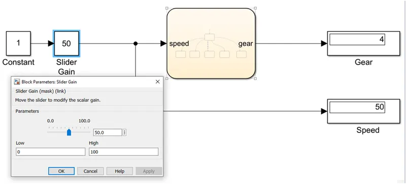
Here gear 4 is displayed at the speed of 50 km/h.
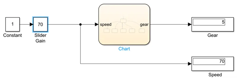
Here gear 5 is displayed at the speed of 70 km/h.
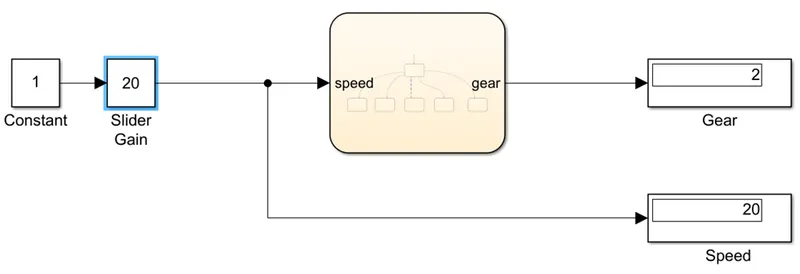
Here gear 2 is displayed at the speed of 20 km/h.
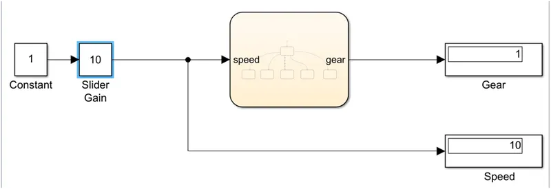
Here gear 1 is displayed at the speed of 10 km/h.
Here gear 3 is displayed at the speed of 40 km/h.