Week - 4
1)
AIM:
control logic of a “washing machine” using Stateflow as per given sequence:
- If the power supply is available, the system gets activated
- If the Water supply is not available, stop the process & indicate through LED
- Soaking time should be 200s followed by Washing time of 100s.
- Then rinsing happens for next 20s & dryer runs for 50s
first of all create a new simulink window.
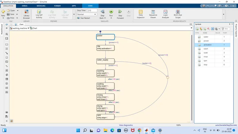
create a chart from search library for the washing machine's states of flow.
first state is power to the machine,so we provide power in a state.if the power is supplied the it will steps to the next step,otherwise it will ends up.
secondly we provide activation of washing machine by another state.
next is water supply state,if the water is on then it will step to next stage,otherwise ends up.
next is washing.we enter entry =1 as working condition otherwise not as exit=0
next is soaking,we enter entry =1 as working condition otherwise not as exit=0
next is rinsing ,we enter entry =1 as working condition otherwise not as exit=0
next is drying,we enter entry =1 as working condition otherwise not as exit=0
next state is end.
in addition we need to specify the inputs ands outputs,
power and water as inputs,other states are output datas.this is done in symbols pan.
now the chart is ready.
next is other cinditions providing.like ON ,OFF and the indicator lights on each states.
sliding switches are provided for ON and OFF.
lambls are provided for each states and lights are setted for on and off conditions respectively.
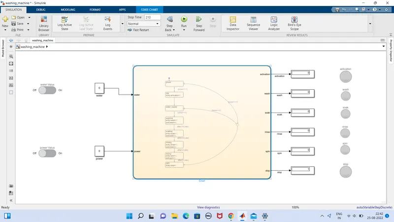
so this is the final stage of the washing machine.
we can check the different conditions of the washing machine.
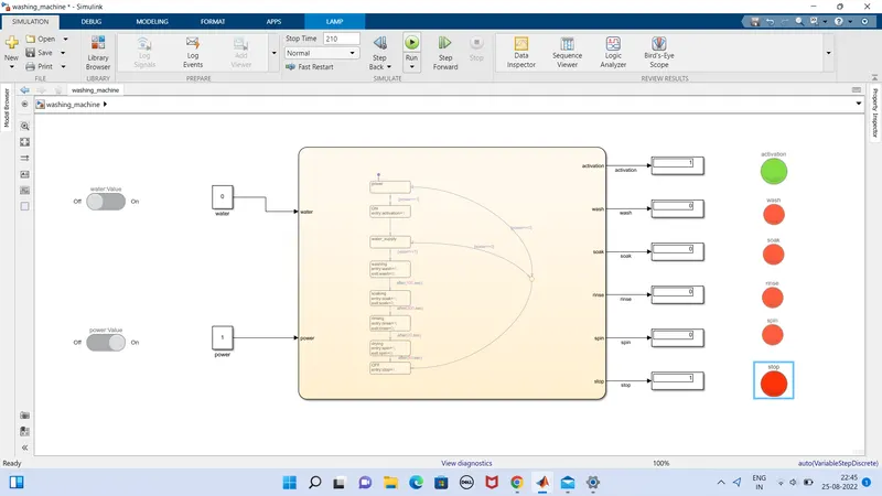
power supply is available and water supply is not available:
if water is supplied and no power supply:
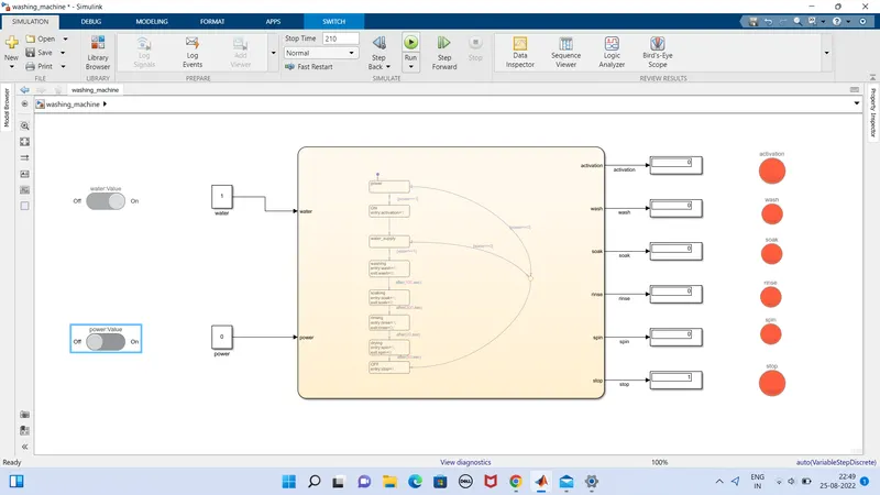
water supplied and power supplied:
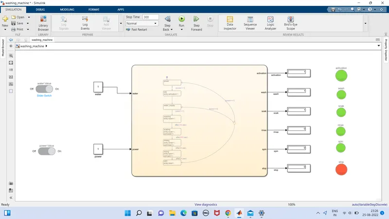
hence our washing machine simulation is done.
2)
AIM:
Make a Simulink chart for the “Gear shift” logic as per below conditions:
Speed Range(kmph) Gear
0 to 15 1
16 to 25 2
26 to 40 3
41 to 60 4
Above 61 5
create a chart as a gear states of gear 1,2,3,4,5 and their respective conditions with speed.
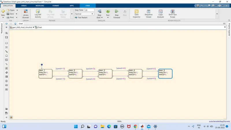
gear 1 with entry=1 and exit=0 as followed in 2,3,4,5 gears .
2nd gear is applied at speed>15
3rd gear is applied at speed>25
4th gear is applied at speed>40
5th gear is applied at speed>60
and downing of these gears in respective of this format.
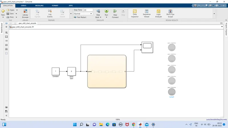
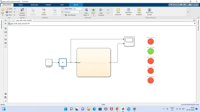
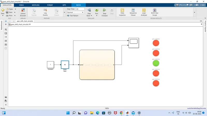
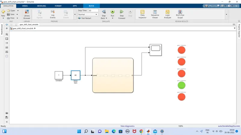
we are providing a slider gain as input of speed and a constant and a scope is in output .
in slider gain we accelerate the speed and in scope the result is viewed.
before running the simulation its look like this ;
when gear 1 is enabled;
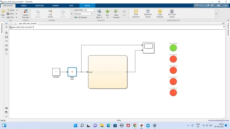
when gear 2 is enabled,
when gear 3 is enabled;
when gear 4 is enabled;
when gear 5 is enabled;
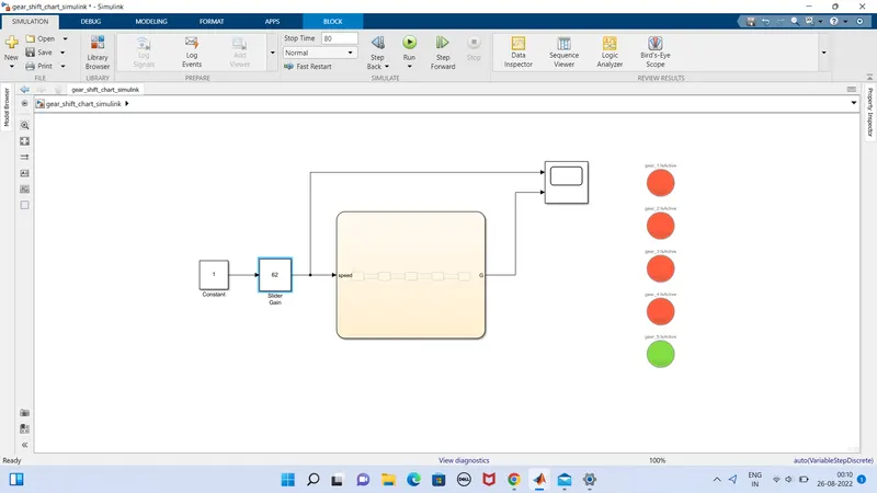
hence all the gears will be enabled at the specific speed which is presetted.
conclution:
so the gear transmission is done with different stages.