Week - 4
Here we have 2 questions

1.	Implement control logic of a “washing machine” using Stateflow as per given sequence:
•	If the power supply is available, the system gets activated
•	If the Water supply is not available, stop the process & indicate through LED
•	Soaking time should be 200s followed by Washing time of 100s.
•	Then rinsing happens for next 20s & dryer runs for 50s

     2. Make a Simulink chart for the “Gear shift” logic as per below conditions:
        Speed Range(kmph)        Gear
              0 to 15                         1
             16 to 25                        2
             26 to 40                        3
             41 to 60                        4
             Above 61                       5
 Give speed input while the simulation is running & display the gear number.


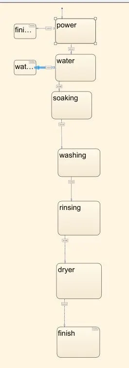
Now we are implementing the control logic of washing machine by using state flow as per sequence In the question


We have sequence process in washing machine

Power on
Water filling
Soaking
Washing
Rinsing
Dryer
Finish

As per question we have time intervals at every stage
Like 200secs for soaking
100 secs for washing
20 secs for rinsing
50 secs for drying

Now we are creating the chart same as per the sequence process at interval times
After that we are adding the 2 lamps, constant blocks, slider switches displays

We have two conditions here
1.	If the power supply is available, the system gets activated
2.	If the Water supply is not available, stop the process & indicate through LED
Now getting to condition one

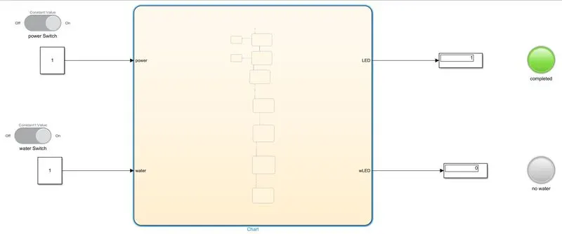
1.	If the power supply is available, the system gets activated
Here you can see the power supply is available and the process is completed and system gets activate
Let see 2nd condition
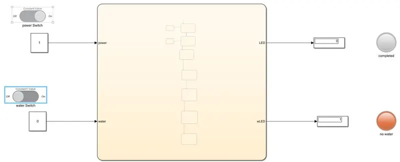
2.	If the Water supply is not available, stop the process & indicate through LED
Here we can see the power supply is on and water supply is off and the red light indicates for no water
Now see

2. Make a Simulink chart for the “Gear shift” logic as per below conditions:
        Speed Range(kmph)        Gear
              0 to 15                         1
             16 to 25                        2
             26 to 40                        3
             41 to 60                        4
             Above 61                       5
 Give speed input while the simulation is running & display the gear number.
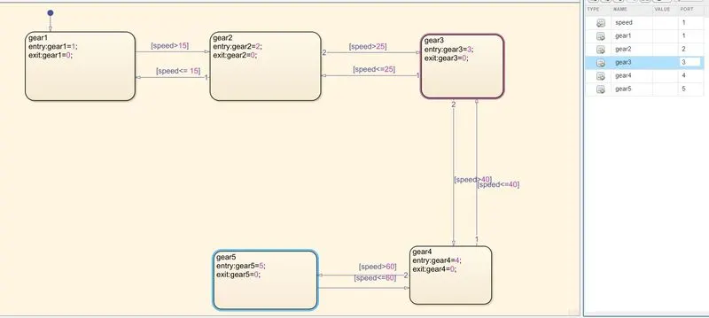
 Now creating a chart for gear shift logic as per given conditions

Here we have conditions for speeds and gears

 0-15 gear-1, 16-25 gear-2, 26-40 gear-3, 41-60 gear-4 and above 61 gear-5

Now we are creating the charts as per the condition
 And creating the inputs and oututs
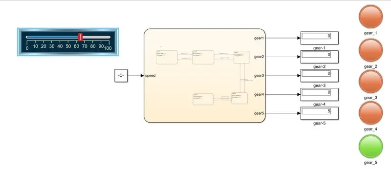
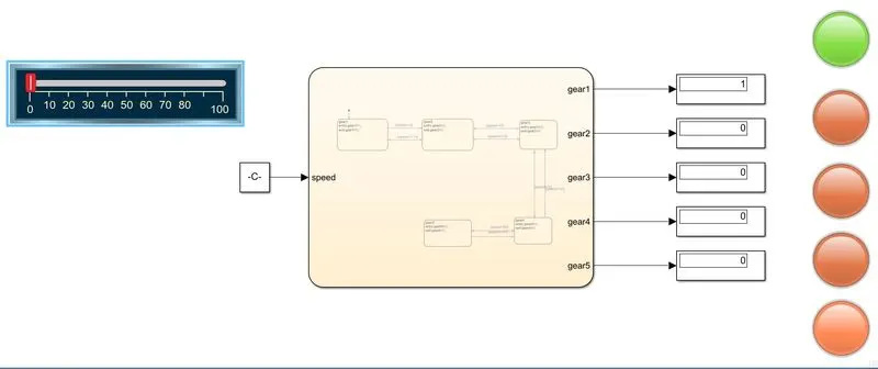
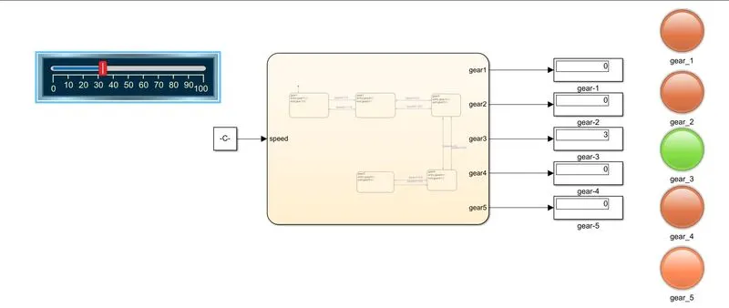
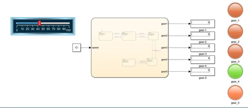
Coming back to the main page adding constants, acceleration meter, displays and lamps
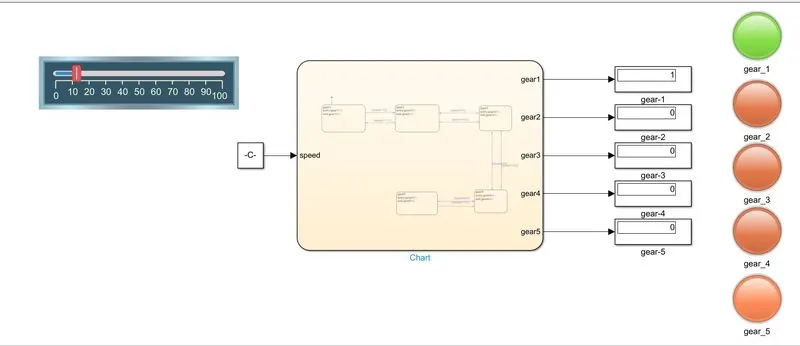
And increasing the speed as per conditions
At below 15 at gear-1
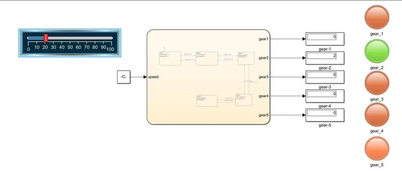
At speed 16-25 at gear-2
At speed 26-40 at gear-3
At speed 41-60 at gear-4
At speed above 61 at gear-5