Week - 4
AIM:
To implement control logic of a "washing machine" using stateflow as per given sequence.
Objective:
In simulink ,implement the control logic of a washing machine using state flow as per given input condition create a model and operation the model logic system and display the output of the results by using lamp indicator.
EXPLANATION:
state flow is a simulink tool to implement the state machine.here model sysytem logic of a washing machine using state flow chart has been done.
step1:
Given Input condition :
- If the power supply is available ,the system get activated
- If the water supply is not available,stop the process and indicate through LED.
- soaking time should be 200sec followed by washing time of 100sec.
- Then rinsing happens for next 20sec and dryer runs for 50sec
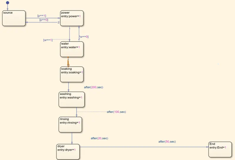
After all the processes have completed turn on the finshed LED
step2:After entering the input conditions in the chart ,go to symbols pane and assigh the given variable( EXample: input,output date,etc.....,)
step3:Given the input values for turning on or off for the power supply and water supply.
condition
if value=1,power and water supply will turn on
if value=0,power supply and water supply will turn off
step4:use 'display' block and 'lamp' indicator to display the results
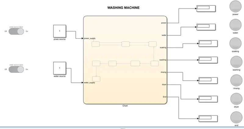
OUTPUTS:
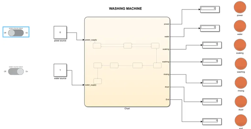
CASE-1:
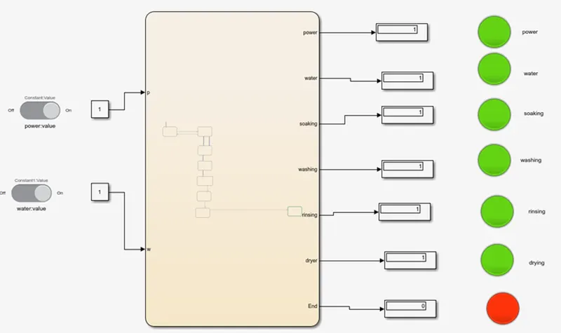
If the power source =0 ,power supply is not available and system will not active.
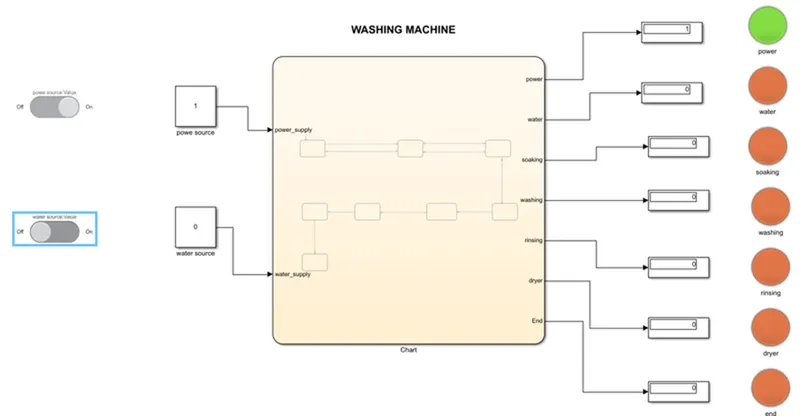
CASE-2:
If the power source =1 and water supply =0,then power supply will be turn on and water supply will be turn off.so system will not activate.
CASE-3:
If the power source=1 and water supply =1 ,then power supply will be on and water supply will be on and so system will activate and after all process completed end lamp will turn on.
AIM:
Make a simulink chart for the"Gear shift" logic as per given conditions.
OBJECTIVE:
EXPLANATION:
Step1: Create a chart and enter the given condition for gear shifting.
Given condition
speed Range(kmph) gear
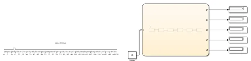
0 to 15 1
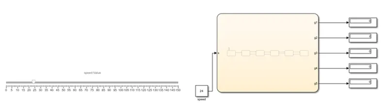
16 to 25 2
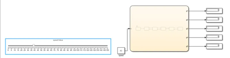
26 to 40 3
41 to 60 4
above 61 5

step2:After entering the input condition in the chart, Go to symbols pane and assign the given variable.
step3: connect the 'silder gain' to vary the speed while simulink is running.
step4: create constant and giving value 1 and 0 for turning on and off.
step5: use 'Display' block to display the gear postion.
OUTPUTS:
case-1: 0 to 15
CASE-2: 16 to 25
CASE-3: 26 to 40
CASE-4: 41 to 60
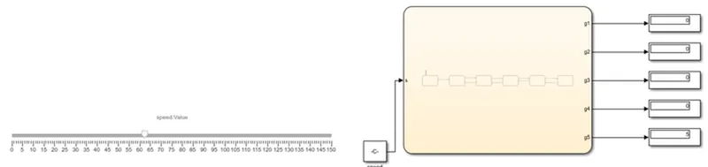
CASE-5: ABOVE 61