Week - 4
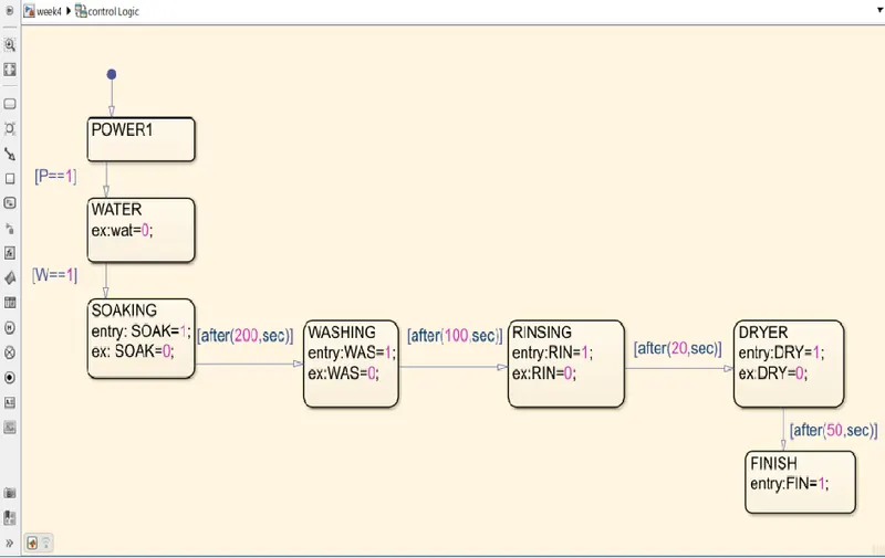
1.Implement control logic of a “washing machine” using Stateflow as per given sequence.
Control logic diagram (stateflow)
Parameters:
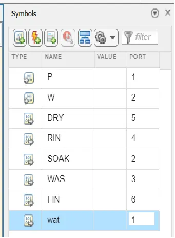
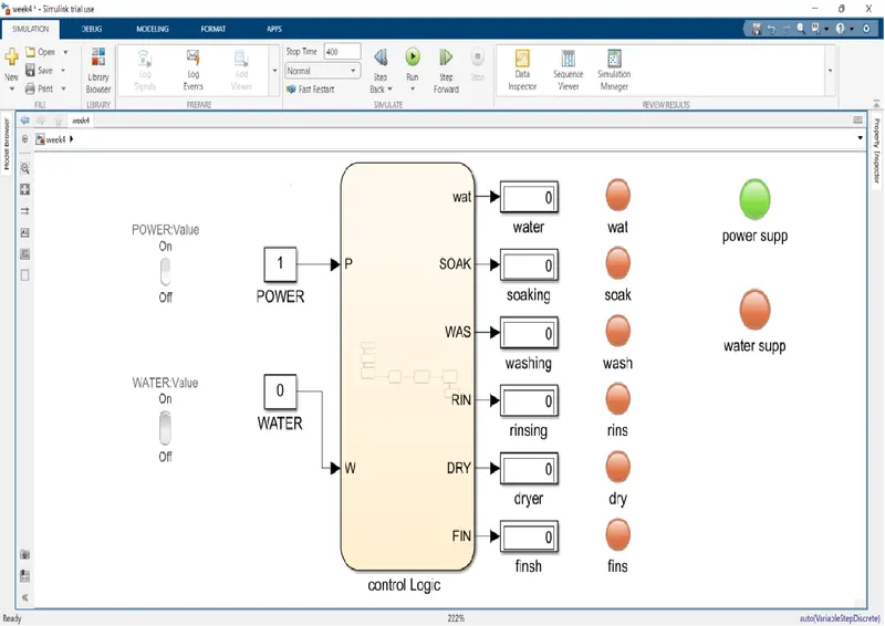
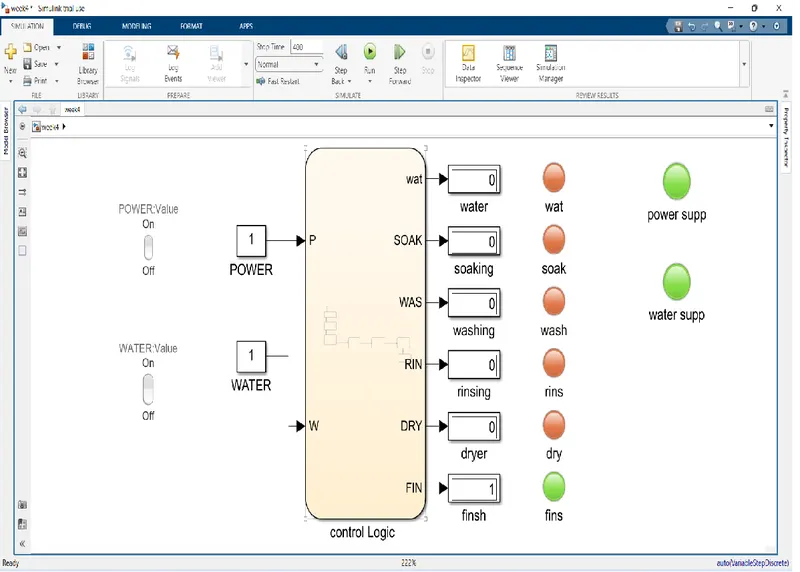
- We have given our water_supply & power_supply as Inputs of the chart.
- We have given water, soak, washing, rinsing, dryer, cycle as Outputs of the chart.
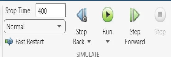
Simulation Time parameters:
The Water supply is not available
- The process is stoped and indicate through Water supply LED IS RED COLOUR
The Water supply is available
- The process is started and indicate through Water supply LED IS GREEN COLOUR
2. Make a Simulink chart for the “Gear shift” logic as per below conditions:
Speed Range(kmph) Gear
0 to 15 1
16 to 25 2
26 to 40 3
41 to 60 4
Above 61 5
Block diagram of model:
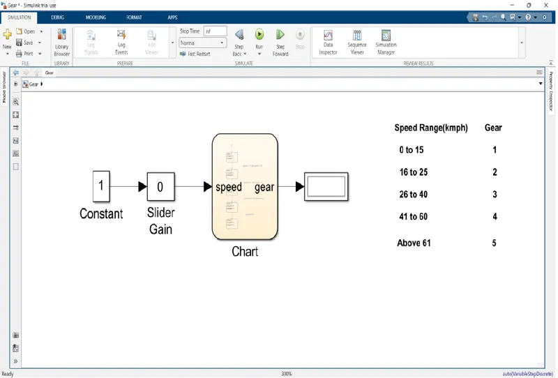
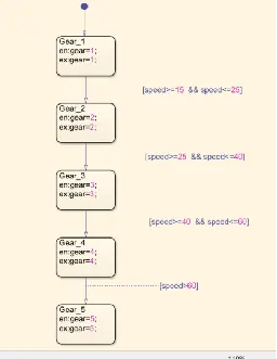
chart diagram:
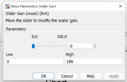
We use slider gain to provide input to the chart
OUTPUT:
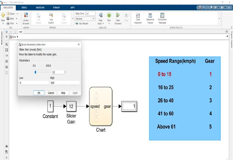
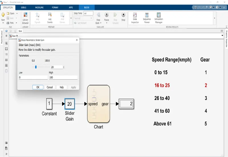
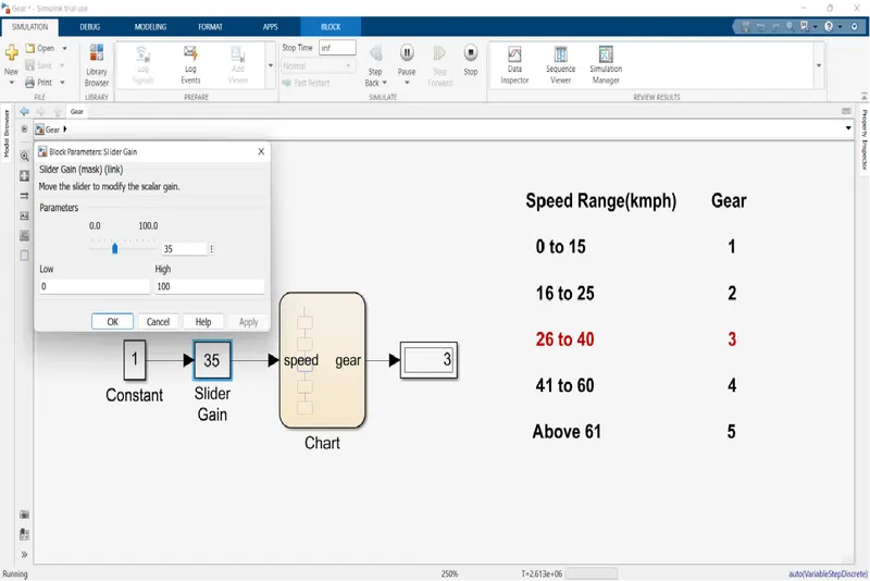
The Output produced is recorded when it's displaying the each gear.
Gear-1:
Speed range: 0 to 15kmph.
Input speed: 12kmph.
Gear-2:
Speed range: 16 to 25 kmph.
Input speed: 20 kmph.
Gear-3:
Speed range: 26 to 40 kmph.
Input speed: 35 kmph.
Gear-4:
Speed range: 41 to 60 kmph.
Input speed: 45 kmph.
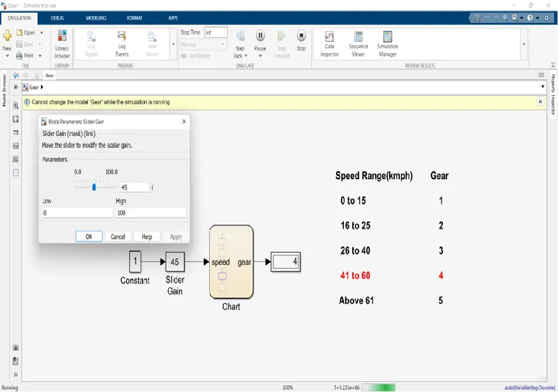
Gear-4:
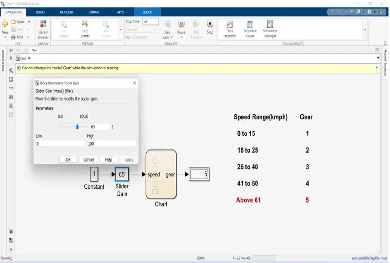
Speed range: above 61 kmph.
Input speed: 65 kmph.