Week - 4
1. Washing machine control logic implementation using stateflow in the sequence of
- If the power supply is available, the system will get activated and glow lamp
- If the Water supply is not available the process will bw stopped and & indicate it through LED
- Soaking time is 200s followed by Washing time of 100s.
- Then rinsing continues for next 20s & dryer runs for 50s
After all the processes have completed turn on the finished LED
- The Process that takes place in the washing machine are
- Filling water
- soaking
- washing
- Rinsing
- Filling water
- Filling water which means filling the water and the washing liquid in to the washing drum
- soaking
- Soaking tis the process of mixing the soap water with the clothes
- Washing
- Washing is the process of removal of strains from the clothes with the help of propeller attached to the drum
- Rinsing
- Rinsing is the process of removal of soap warwe from the clothes
Modeling of Washing machine in Simulink:
these are the things needed for modeling the subs system of washing machine settings:
State flow chart, Constant,Toggle switch,Lamps,Display
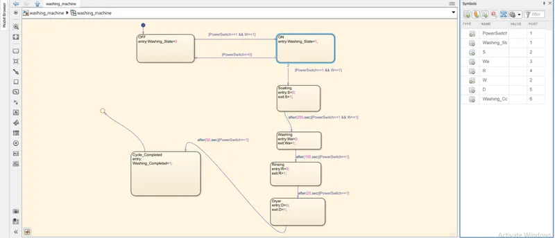
The program and the chart along with the screen shorts are attached
if the power supply is given the value assigned is 1 then the green light glows or if the value is 0 then power suppy is off which indicates red light.
the same for the case of water 0 for no water and 1 for sufficient water, if both the values are 1 then the flow chart gets executed one by one . for each flow the time is being assigned and hence executed.
Stateflow diagram:
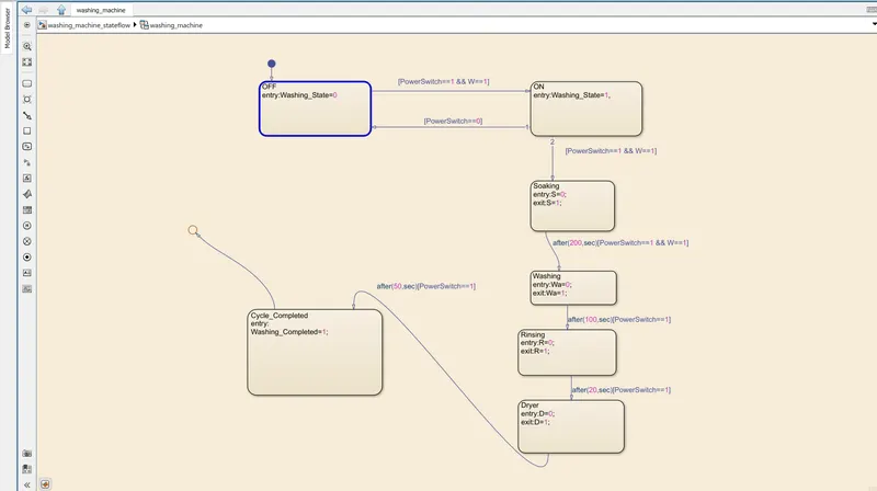
Below attached are simulink results of washing machine at different switching conditions:
a)
b) Washing power state ON with all the processes ON.
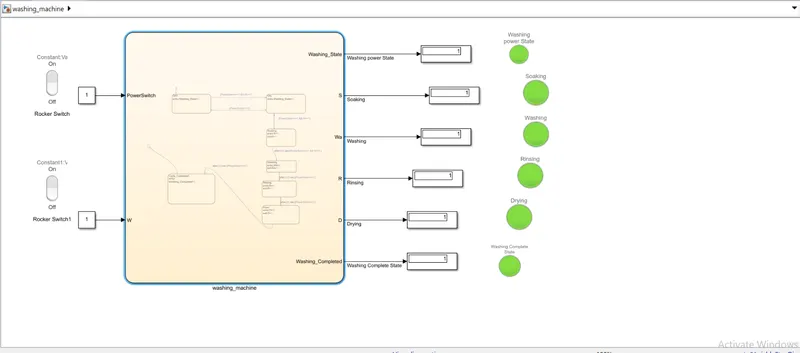
c) Washing power state ON with all the processes OFF.
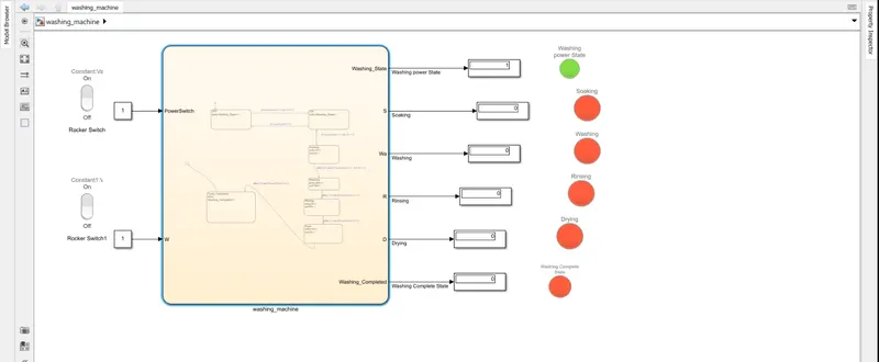
d) Washing power state ON with soaking processes ON.
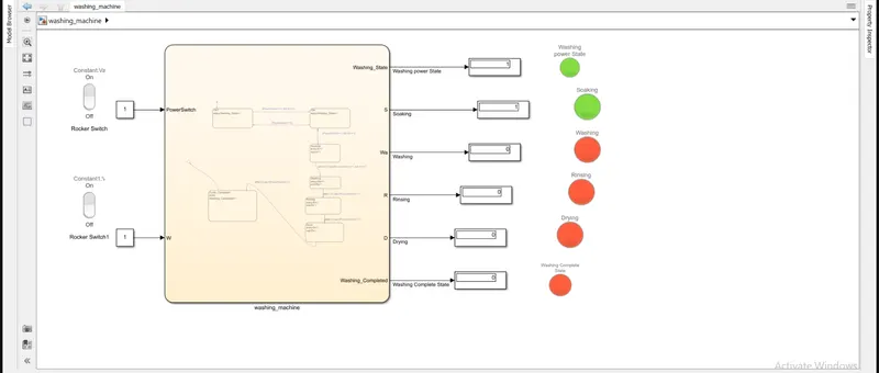
e) Washing power state ON with soaking and washing processes ON.
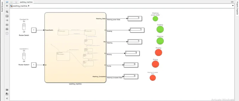
f) Washing power state ON with soaking, washing and rinsing processes ON.
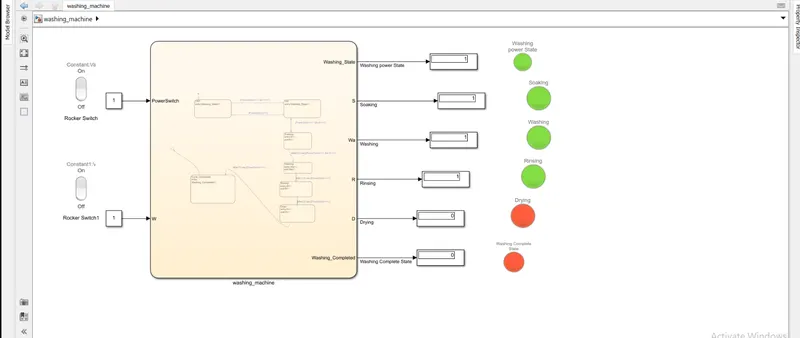
2. To Make a Simulink chart for the “Gear shift” logic as per below conditions:
Speed Range(kmph) Gear
0 to 15 1
16 to 25 2
26 to 40 3
41 to 60 4
Above 61 5
To Give speed input while the simulation is running & display the gear number.
Answer :
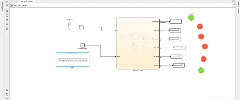
The change of gear plays an important role in automobiles and also in all the other machineries where the engine or the motor speed needs to be modified for our requirements.
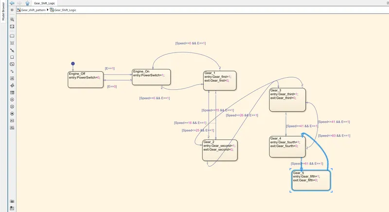
here the state flow is given for the speeds namely 1,2,3,4,5 speed gear box
if the engine speed in 1 the green light glows which indicates the engine is ON, if the value is 0 then red light glows with it
The transitions condition for the gear shift is decided as
Speed>15 shift to G=2; Speed>25 shift to G=3; Speed >40 shift to G=4 ;Speed>60 shift to G=5
when the speed is from 0-100 kmph
similarly in reverse direction
Speed<60 shift to G=4; Speed<40 shift to G=3; Speed<25 shift to G=2; Speed<15 shift to G=1
when the speed is from 100-0 Kmp
green light represents the gear position
Gear shift pattern stateflow diagram:
Below attached are simulink results of gear shift patterns:
a) When power switch is ON and gear 3 is ON
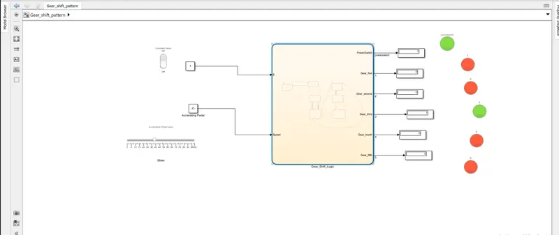
b) When power switch is ON and gear 4 is ON
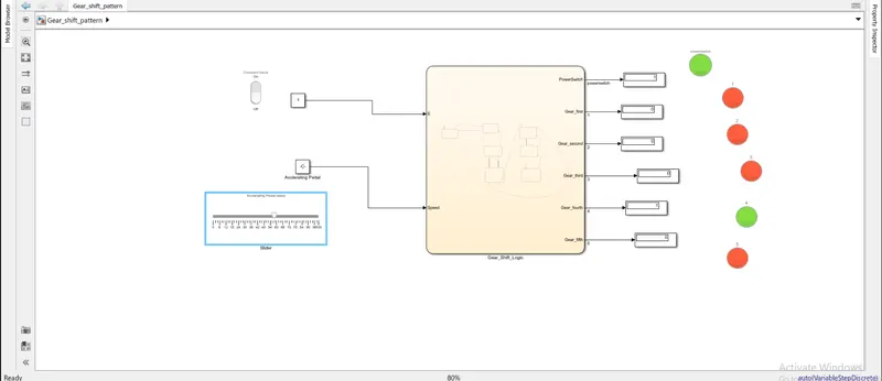
c) When power switch is ON and gear 4 is ON
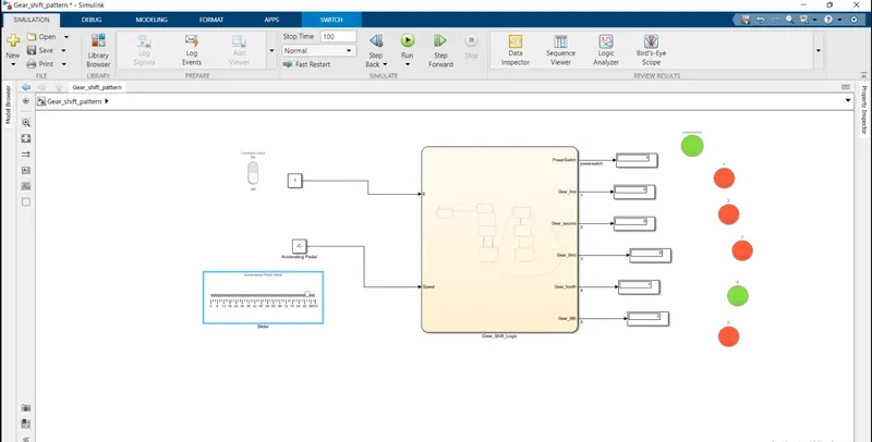
d) When power switch is ON and gear 5 is ON
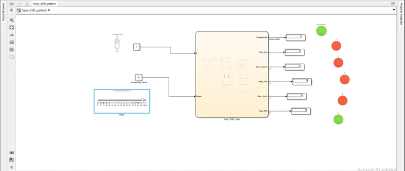
e) When power switch is ON and gear 3 is ON