Week - 4
Aim:
- Implement control logic of a “washing machine” using Stateflow as per given sequence:
- If the power supply is available, the system gets activated
- If the Water supply is not available, stop the process & indicate through LED
- Soaking time should be 200s followed by Washing time of 100s.
- Then rinsing happens for next 20s & dryer runs for 50s
After all the processes have completed turn on the finished LED
2. Make a Simulink chart for the “Gear shift” logic as per below conditions:
Speed Range(kmph) Gear
0 to 15 1
16 to 25 2
26 to 40 3
41 to 60 4
Above 61 5
Give speed input while the simulation is running & display the gear number.
Procedure:
Working Principle of washing machine .
Soaking: At first i have to give power supply and water supply in washing machine . and getting first step by soaking clothes in detergent powder .
it tooks 42 minutes , at this time 27 min took to soak the water properly and the rest minutes it washes the clothes . after soaking i have to move on next steps washing.
Washing: After soaking gets done the clothes are washed it tooks at least 15 minutes .
Rinsing : After soaking and rinsing we have to move in rinsing .he dirty, soapy water is drained, then the washing machine is refilled and your clothes are "rewashed" in clean water . Spin: All the water is drained completely, then your clothes are spun very fast and excess water is removed thanks to centrifugal force.
Drying: The last step is to drying the clothes .
Control Logic of State flow of washing Machine :
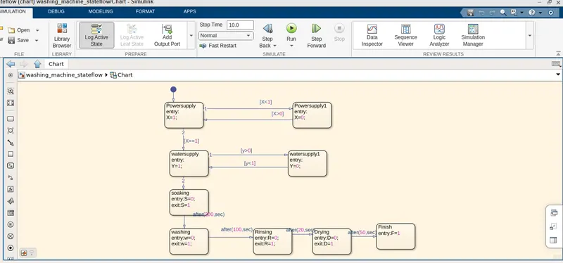
In this above figure from simulink we made chart in state flow . at first we give power supply as input and then we give water supply to the system . keep soaking time 200second
after that it uses washing process and rinsing for 100 seconds and drying for 20 seconds and then finished .
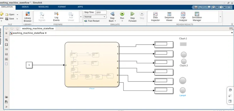
In this above simulink model we use power supply and water supply as input and keep the information as given in the above.
we uses lamp for indicating the procees done by washing machine .
Gear Ratio: In gear shift logic system first we have to make chart in simulink as given conditions in the questions .
in gear box system we use speed as input and vehicle motion, and gear as this gives us output for given input in gear shift logic
first we have to start from speed 0 to 15 , at first gear 1. 16 to 25, at second gear , 26 to 40 at 3rd gear , 41 to 60 at 4th gear and avobe 60 we have to use 5th gear .
we have to use Odometer and slider gain , slider switch , for simulation .
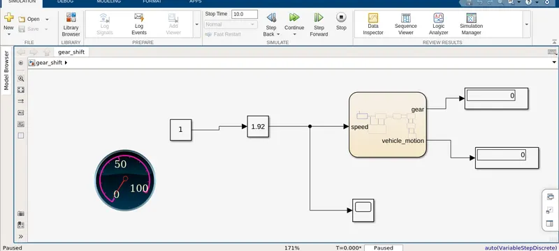
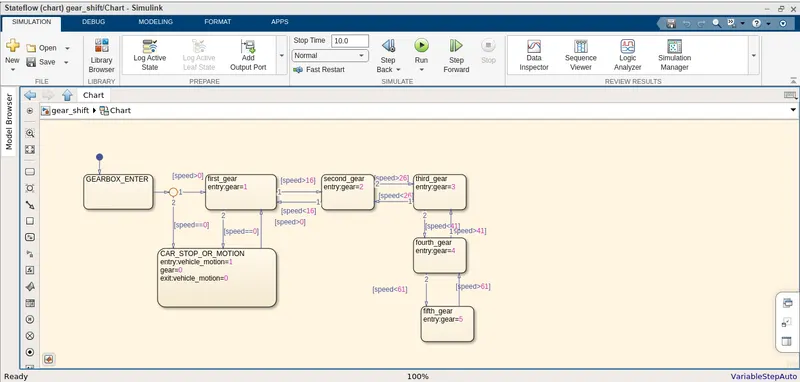
In the above figure we use state flow chart for desiging gear shift in this chart we enter gear box as input at speed greater than zero condtion .