Week - 4
Ans1. Simulink model explanation
- Chart: A finite state machine is a representation of an event-driven system . In an event driven system, the system respond to a event by making a transition from one state to another. The transition accure the condition defining the change is true.
- Display: The display block shows the value of the input data. you can specify the frequency of the display.
- Constant: The constant block shows a real or complex constant value singnal.Use the block to provide a constant signal input.
- Lamp: The lamp block display a colour indicating the value of the input signal.we can specify pairs of input values and colour to provide the information during the simulation.
- Rocker switch: The Rockers switch block toggles the value of the connected block parameter between two values during simulation.
Control logic of washing machine:
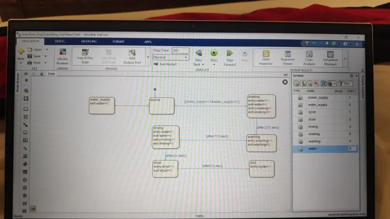
Explanation :
- FIRST STAGE POWER SUPPLY:In the control logic diagram starting state is created with two transition condition, 1st is power supply=1 and 2nd is water supply=1 that means both supply on.
- SECOND STAGE SOAKING: It is used to dip clothes in detergent water to remove dirt from the clothes.This function is available with wash timer, In 200sec is used for soak.
- THIRD STAGE WASHING: In this stage only washing is done with time period of 100 sec.
- FORTH STAGE RINSING: The Dirty soapy water is drained, then the washing machine is refilled and your clothes are rewashed in clean water. this rinsing process will take 20 sec.
- FIFTH STAGE DRYER: In this process Pushing warm dry air through your wet washing to extract moisture in 50 sec.
Result:
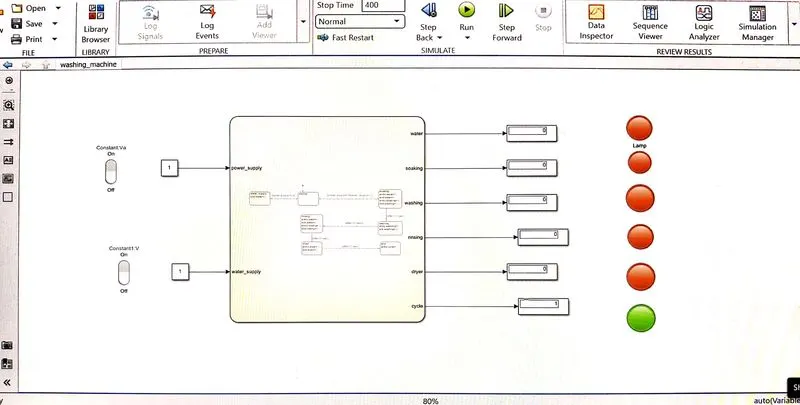
Condition 1:(Power supply & water supply both activated)
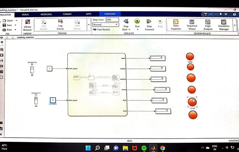
Condition 2: (Power supply activated & water supply not activated)
In this process indicator show water supply not present,then terminate the process showes with indicator.
Ans2. Objective: Make gear shift logic with diffrent speed..
State flow diagram of gear shift model using simulink chart :
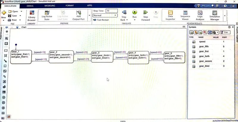
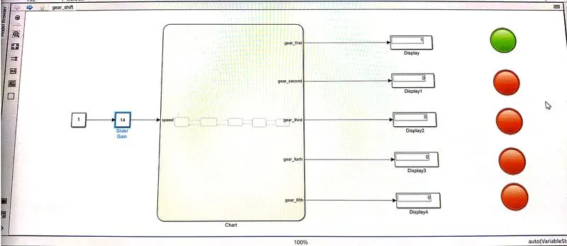
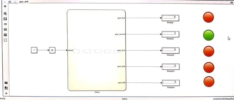
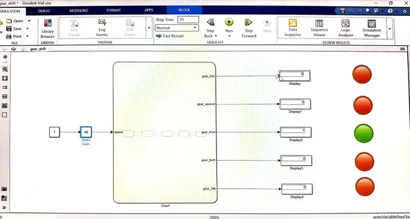
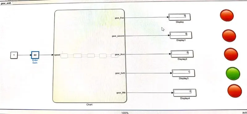
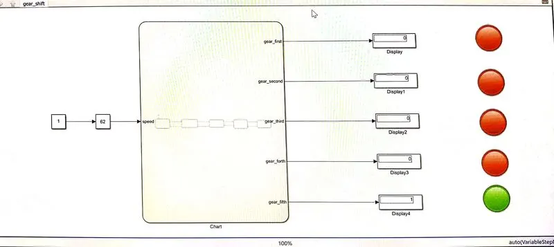
Explanation: The speed ranges from 0 to 100 and the slider is used to send the input. The 1st gear has speed values from 0 to 15 so the entry condition for the 1st gear is 0<=speed and speed<=15 and the exit condition is when the speed greater than 15.Similarly for 2nd gear, the entry condition is 16<=speed and speed<=25 the exit condition is when speed<16 and speed>25. In the same way for each gear, the entry and the exit condition are specified and the out is mapped to the lamp and the display block.
Result:
This is a Gear shift result after simulation . we simulate all speed given in question.
First gear: speed (0 to 15)
Second gear: speed(16 to 25)
Third gear: speed (26 to 40)
Forth gear: Speed(41 to 60)
Fifth gear: speed (above 61)
Slider block:The Slider block tunes the value of the connected block parameter during the simulation. You can modify the range of the Slider block's scale to fit your data.