Week - 4
- Implement control logic of a “washing machine” using Stateflow as per given sequence:
- If the power supply is available, the system gets activated
- If the Water supply is not available, stop the process & indicate through LED
- Soaking time should be 200s followed by Washing time of 100s.
- Then rinsing happens for next 20s & dryer runs for 50s
After all the processes have completed turn on the finished LED
Ans :- EXPLANATION OF CONTROL LOGIC OF A WASHING MACHINE USING STATEFLOW
BLOCK USED:- (A) CONSTANT BLOCK
(B) CHART
(C) DISPLAY
(D) SCOPE
(E) SLIDER SWITCH
(F) LAMP
STEP1:- Create a chart and enter the given conditions into the stateflow chart.
Given inputs conditions:-
- If the power supply is available, the system gets activated.
- If the Water supply is not available, stop the process & indicate through LED.
- Soaking time should be 200sec followed by Washing time of 100sec.
- Then rinsing happens for next 20sec & dryer runs for 50ssec.
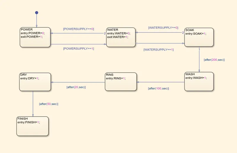
After all the processes have completed turn on the finished LED
STEP2 :- After all conditions is entered in the flow chart then click on symbols pane assign inputs and outputs of stateflow chart.
Our simulink model of washing machine is given below
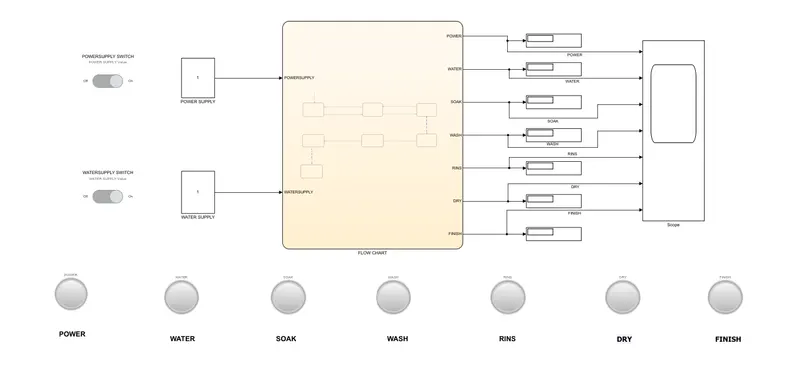
Our input is POWERSUPPLY and WATERSUPPLY and output is POWER ,WATER, SOAK, WASH, RINS, DRY, FINISH which is shown in above simulink model.
Step3:- If our simulink model is ready to run then click on run button and observe the output.
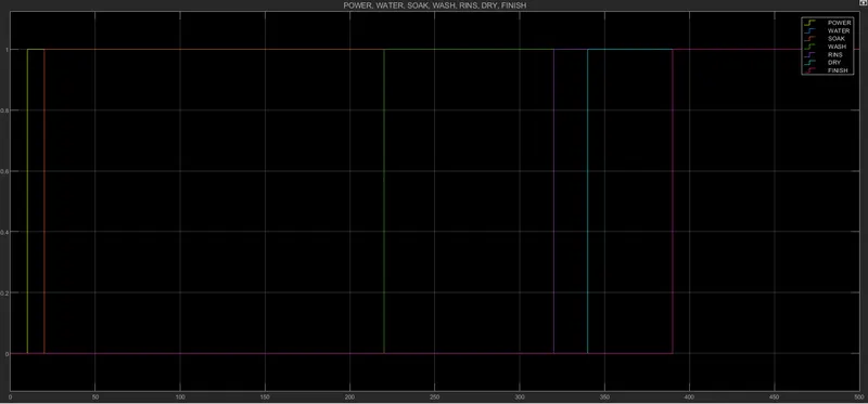
FIRST CONDITION:- IF POWER SUPPLY IS ON AND WATER SUPPLY IS OFF .
THEN POWER LAMP IS ON WHICH IS INDICATE WITH GREEN COLOUR AND OTHER LAMP IS OFF WHICH IS INDICATE WITH RED COLOUR.
THAT MEANS IF THE WATER SUPPLY IS NOT AVAILABLE NEXT PROSSES WILL BE STOP.
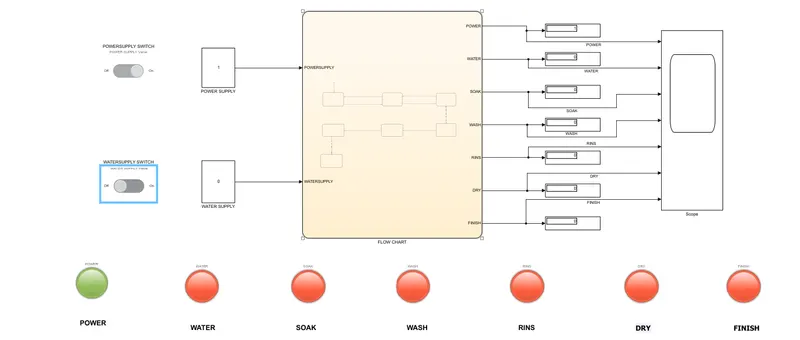
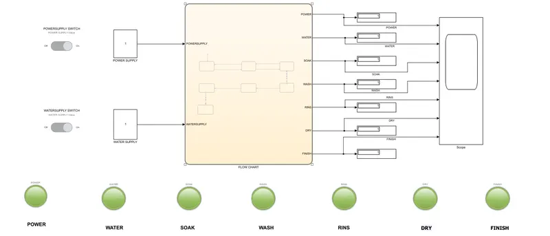
SECOND CONDITION:- IF POWER SUPPLY IS ON AND WATER SUPPLY IS ALSO ON THEN ALL LAMPS INDICATES GREEN COLOUR.
THAT MEANS ALL THE PROCESSES ARE SUCCESFULLY COMPLECTED.
WHICH IS SHOWN IN BELOW SIMULINK MODEL.
SCOPE OUTPUT:-
2. Make a Simulink chart for the “Gear shift” logic as per below conditions:
Speed Range(kmph) Gear
0 to 15 1
16 to 25 2
26 to 40 3
41 to 60 4
Above 61 5
Give speed input while the simulation is running & display the gear number.
Ans :- EXPLANATION OF CONTROL LOGIC OF A GEAR SHIFT USING STATEFLOW
BLOCK USED:- (A) SLIDER
(B) GAUGE
(C) CONSTANT BLOCK
(D) CHART
(E) SCOPE
(F) DISPLAY
STEP1:- Create a chart and enter the given conditions into the stateflow chart.
Given inputs conditions:-
Speed Range(kmph) 0 to 15 16 to 25 26 to 40 41 to 60 Above 61
Gear 1 2 3 4 5
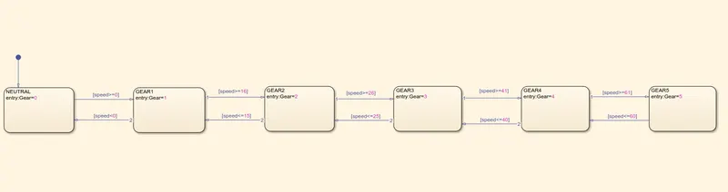
Give speed input while the simulation is running & display the gear number. That means input is speed and output is gear which is shown in our simulink model.
STEP2:- After all conditions is entered in the flow chart then click on symbols pane assign inputs and outputs of stateflow chart.
Our simulink model of gear shift is given below
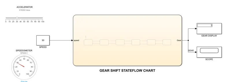
Above simulink model shows ACCELERATOR and SPEEDOMETER is connect to input constant speed block.
output is shown in scope and gear display.
In this simulink model speed is 30 km/hr which is shown in speed block as well as speedometer.
If the speed is between 26 to 40 km/hr then gear no 3 will be activated as per our given condition.
Gear position is display in above simulink model.
Likewise, changing the speed in the speedometer according to the given condition, Gear position will be change.
SCOPE OUTPUT :-
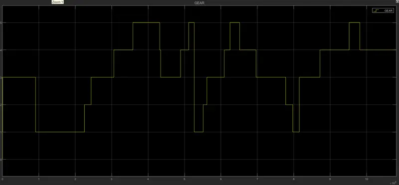
Scope Output is shows gear position is change according to speed with respect to time.