Week - 4
- Implement the control logic of a “washing machine” using Stateflow as per the given sequence:
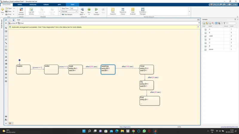
this chart contains logic for soaking, washing, rinsing, and drying. Power and water are considered as input unless both are on the machine won't work.
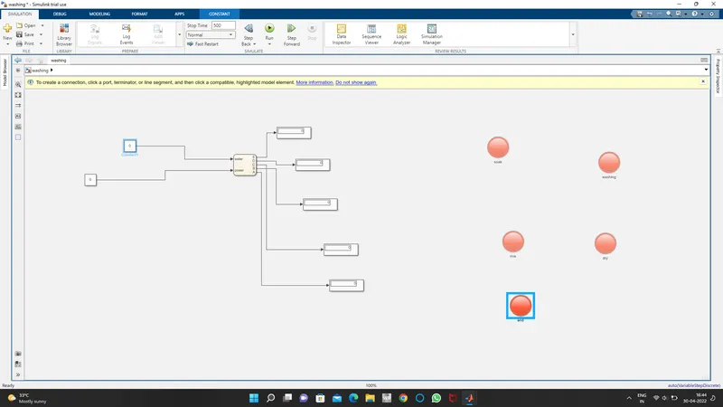 power and water supply is off so that all indicators are showing red(not working).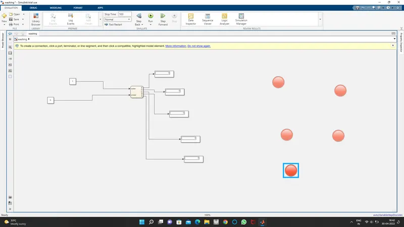
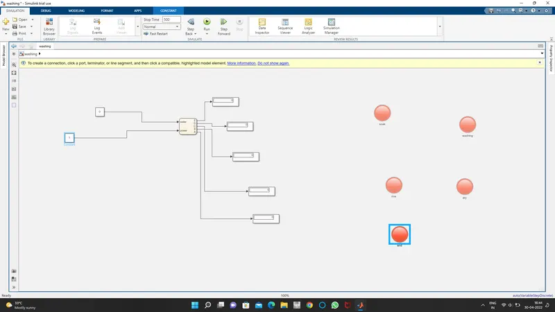 it shows that if either one of the power and water supply is off then the machine is not going to work.
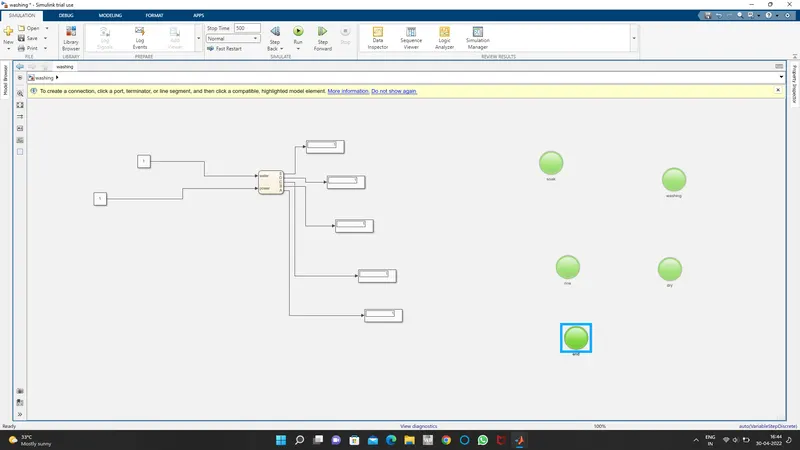 in this both power and water supply is on hence machine is going to work.
2. Make a Simulink chart for the “Gear shift” logic
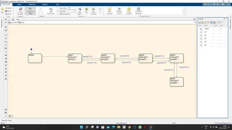 chart for different gears is created by using mathematical conditions(< >).
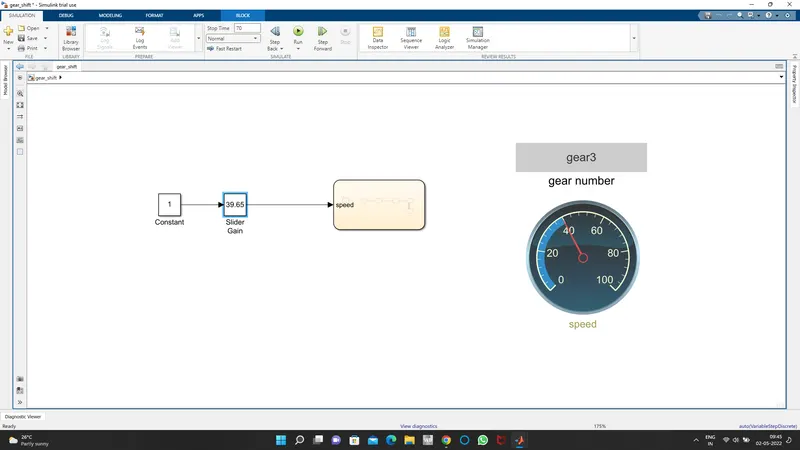
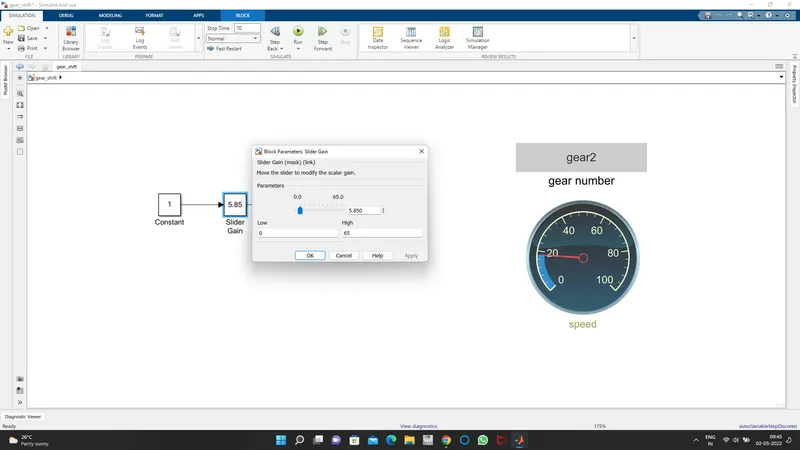
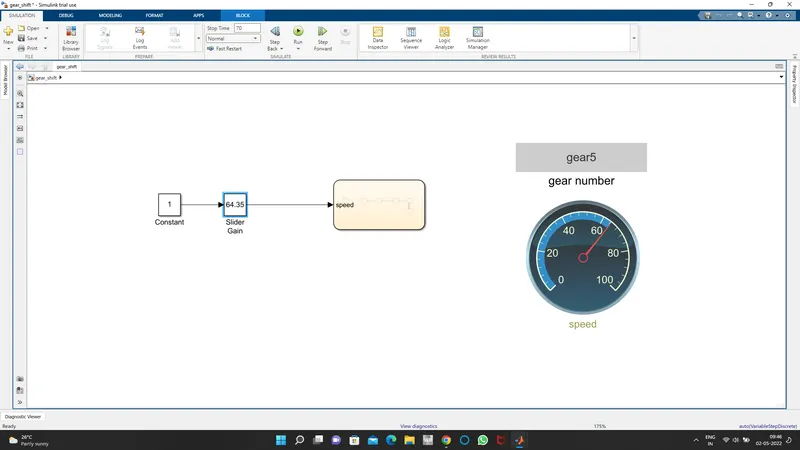
- slider gain is used for providing the speed values to the gearbox.
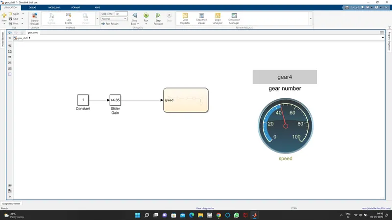 speed=44.85 unit and gear indicating gear no.4
 - similarly at different speeds