Week - 4
Q.1. Implement control logic of a “washing machine” using Stateflow as per given sequence:
- If the power supply is available, the system gets activated
- If the Water supply is not available, stop the process & indicate through LED
- Soaking time should be 200s followed by Washing time of 100s.
- Then rinsing happens for next 20s & dryer runs for 50s
After all the processes have completed turn on the finished LED
State- flow:
Systematic solution of a problem is possible with sequential, unambigious and realizable finite process step set. This set is called “algorithm” and it is one of the most important part of the programming languages. In this study, it is represented how to learn algorithm by using Simulink stateflow.
Control Logic of a washing machine:
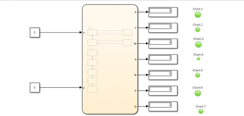
It checks for the extend of dirt and grease, the amount of soap and water to add, direction of spin, and so on. The machine rebalances washing load to ensure correct spinning. Else, it reduces spinning speed if an imbalance is detected. Even distribution of washing load reduces spinning noise.
The two inputs are given for the power and water supply. Once the inputs are given outputs are displayed by the flow chart as per the given sequence. The process is completed by green light as displayed.
Result:
The control logic of a washing machine using stateflow is processed as per the given sequence and LED lights are turns to the green colour and the system is completed.
Q.2.Make a Simulink chart for the “Gear shift” logic as per below conditions:
Speed Range(kmph) Gear
0 to 15 1
16 to 25 2
26 to 40 3
41 to 60 4
Above 61 5
Give speed input while the simulation is running & display the gear number.
Gear shift logic:
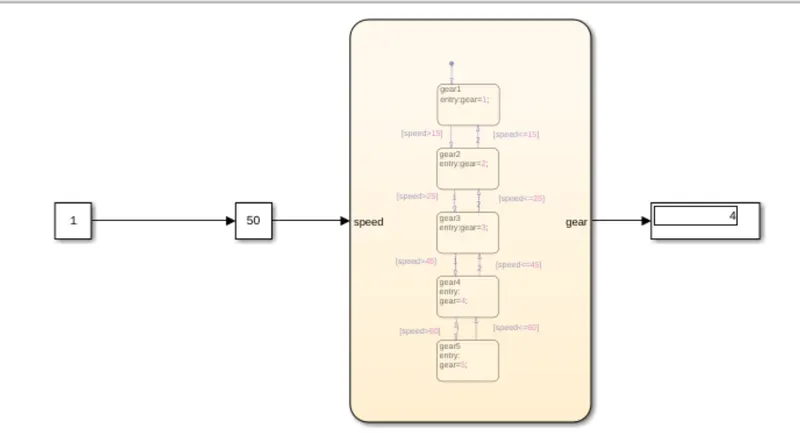
A gear shift mechanism for a manual transmission includes a shaft axially movable for selecting shift planes and rotatable for engaging the gears defining the shift planes. The shaft is held in a reference shift plane by two helical springs.
If speed is less or equal to 15 then gear is 1.
If speed is greater than 15 and less than 25 gear is 2.
If speed is greater than 25 and less than 40 gear is 3.
If speed is greater than 40 and less than 60 gear is 4.
If speed is greater than 60 then gear is 5.
Result:
A Simulink model is created for the gear shift logic and using slider gain the values are obtained.