Week - 4
AIM
1. To implement control logic of a “washing machine” using Stateflow as per given sequence.
2.To make the simulink chart for the “Gear shift” logic as per below conditions.
STATEFLOW OF WASHING MACHINE:
what is a stateflow?
Stateflow provides a graphical language that provides state transition diagrams ,flow charts,state transition tables, and truth tables.
PROCEDURE:
INPUT CONDITIONS:
- If the power supply is available, the system gets activated
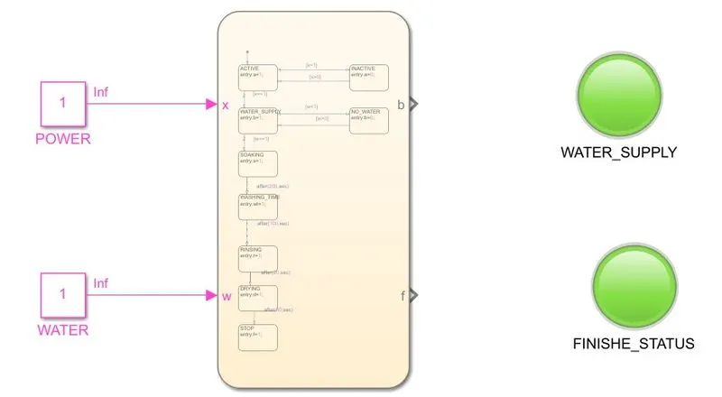
- If the Water supply is not available, stop the process & indicate through LED
- Soaking time should be 200s followed by Washing time of 100s.
- Then rinsing happens for next 20s & dryer runs for 50s.
EXPLANATION:
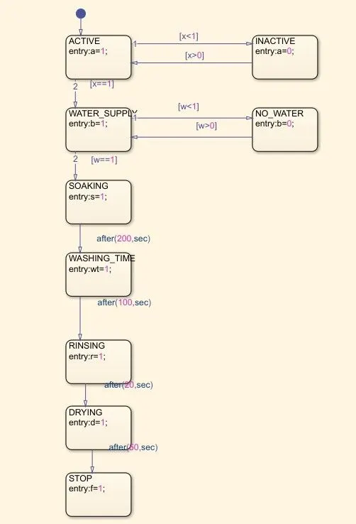
As per the given conditons , we need to create a stateflow using the chat .
First we need give the power supply to the machine ,and then the system get activated. In simulink terms, the state should be active if the power supply is on, else the state is not active .By creating a variable X ,we can check whether the state is either active or inactive.
After the power supply is on , We need to turn on the water supply,if the water is filled the state named water supply gets activated otherwise the state remains low and it will be indicated through the LED.
Then the soaking time should be 200s followed by the washing time of 100s.
After the soaking process , the rinsing happens for 20s and finally the dryer runs for 50s .
After the completion of all the procces the finished state will be activated, and it will also be idicated through the LED.
STATEFLOW DIAGRAM:
OUTPUT:
STATEFLOW FOR THE GEAR SHIFT:
INPUT CONDITIONS:
Speed Range(kmph) Gear
0 to 15 1
16 to 25 2
26 to 40 3
41 to 60 4
Above 61 5
EXPLANATION:
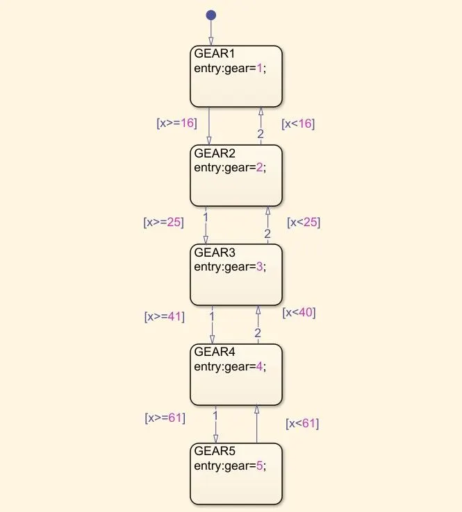
The stateflow for the gear shift logic use the speed range to decide the gear.
The speed will be varied by the slider gain which is the input data for the chat,here we declared the speed as variable x.
If the speed is between 0-15, the state remains in Gear 1. If the speed ranges between 16 to 25, the state changed to Gear 2.
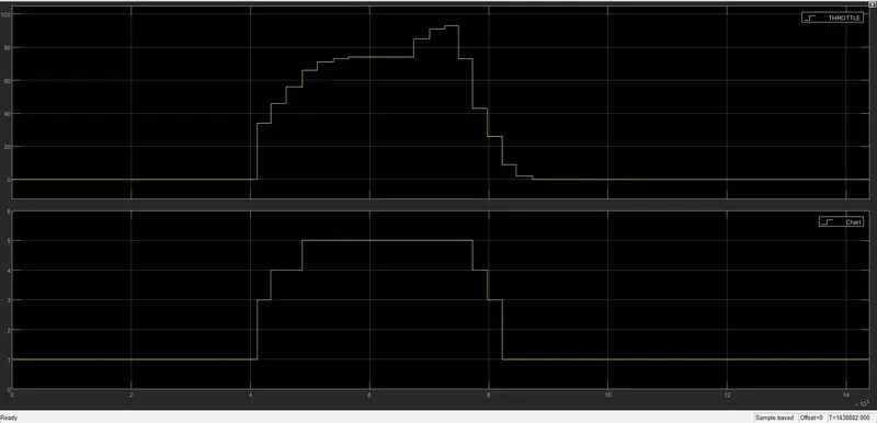
We can see the change of the gear using the scope.
STATEFLOW DIAGRAM;
OUTPUT:
RESULT:
The stateflow for the washing machine is done using the chart and gear shift logic also implemented in the stateflow .