Week - 4
1) Implementing the control logic of a 'wasing machine' using stateflow sa per given sequence.
* Blocks Used:
Chart: A finite state machine is a representation of an event-driven system, in an event driven system, yhe system responds to an event by making a transition.
Display: Display block shows the value of the input data. You can specify the frequency of the display, for numeric output data and you can also specify the format of the display.
Constant: The Constant block generates a real value signal, use this block to provide a constant signal input.
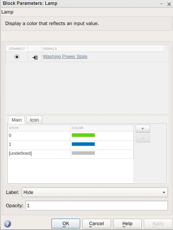
Lamp:The Lamp block displays a color indicating the value of the input signal, you can use this block with other dashboard blocks to build an interactive dashboard of controls and indicators for your model.
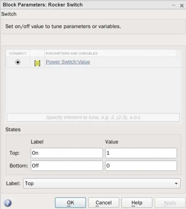
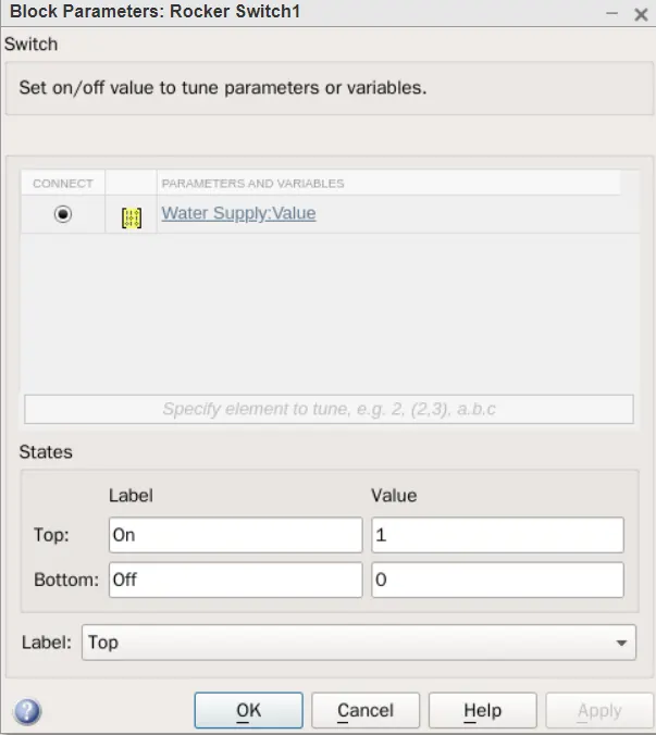
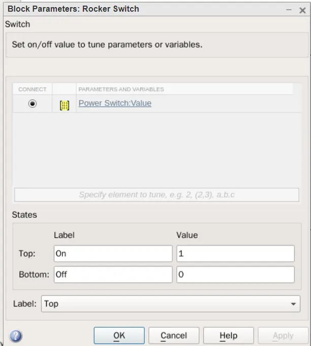
Rocker Switch: The Rocker Switch blocks toggles the value of the connected block parameter between two values during simulation.
* Simulink Model Block Diagram:
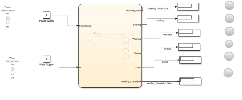
* Logic:
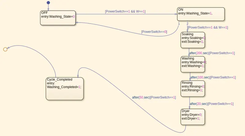
* Rocker Switch Parameters:
* Lamp Parameters:
*) The system will run whem the power supply is available.
*) If the water supply is not available the system will not run.
*) The total running time of the system is 370 seconds.
* Conclusion: Implementation of control logic of a 'washing machine' using a stateflow is simulated as per the given sequences.
2) To make a simulink chart for the 'Gear Shift' logic as per the given conditions.
* Blocks Used:
Chart: A finite state machine is a representation of an event-driven system, in an event driven system, yhe system responds to an event by making a transition.
Display: Display block shows the value of the input data. You can specify the frequency of the display, for numeric output data and you can also specify the format of the display.
Constant: The Constant block generates a real value signal, use this block to provide a constant signal input.
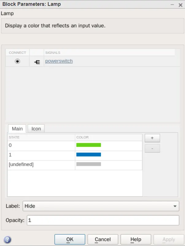
Lamp:The Lamp block displays a color indicating the value of the input signal, you can use this block with other dashboard blocks to build an interactive dashboard of controls and indicators for your model.
Rocker Switch: The Rocker Switch blocks toggles the value of the connected block parameter between two values during simulation.
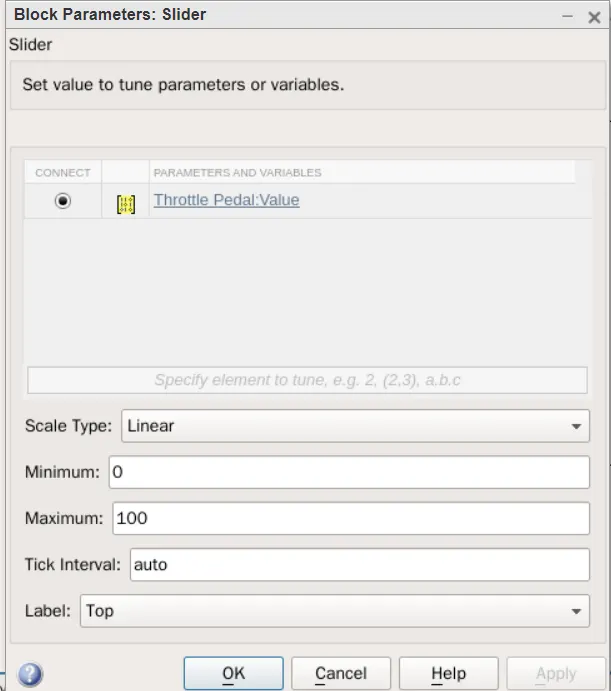
Slider: The Slider block tunes the value of the connected block parametr during the simulation. Use the slider bock with the other dashboard blocks to create an interactive dashboard to control your model.
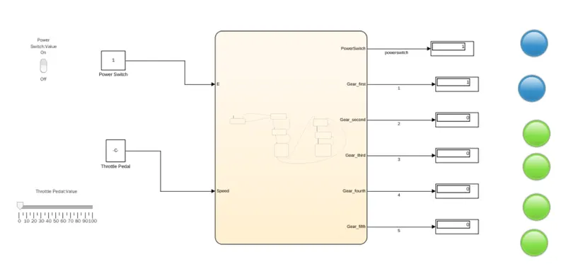
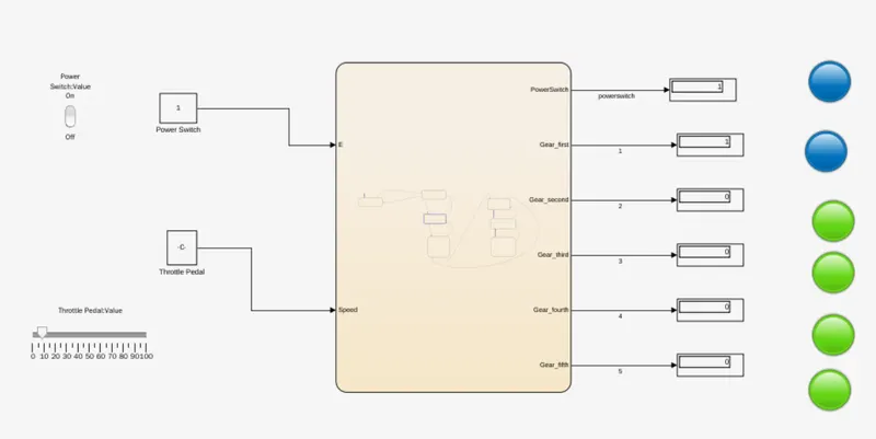
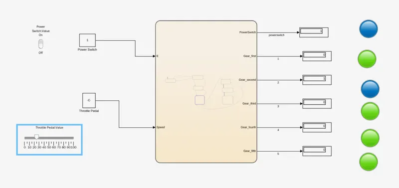
* Simulink Model Block Diagram:
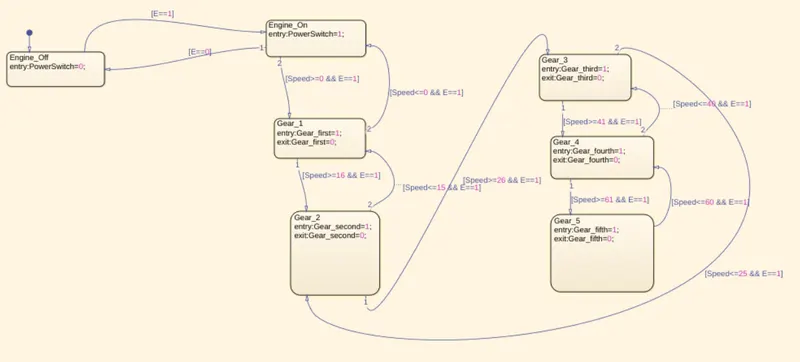
* Logic:
* Rocker Switch Parameters:
* Slider Block Parameters:
* Lamp parameters:
* Condition: 0-15(kmph) - Gear 1.
* Condition: 16-25(kmph) - Gear 2.
* Condition: 26-40(kmph) - Gear 3.
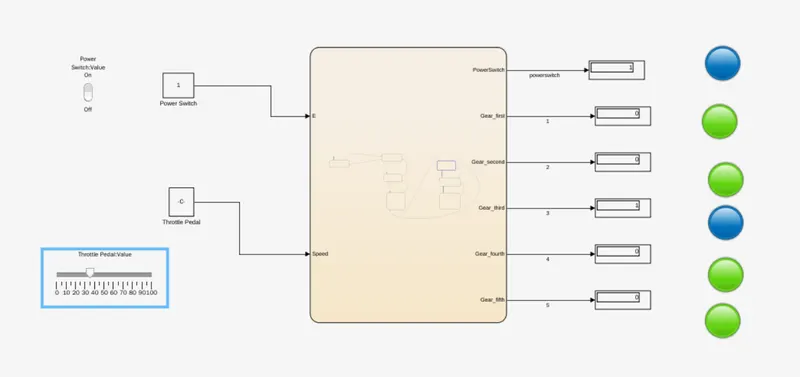
* Condition: 41-60(kmph) - Gear 4.
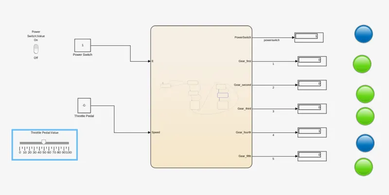
* Condition: Above 61(kmph) - Gear 5.
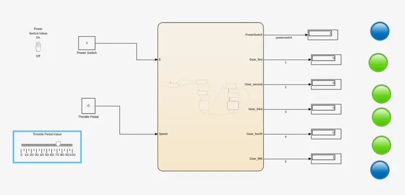
Conclusion: The Simulink Chart for the ;Gear Shift; logic has been created as per the given conditons and Simulated.