Week - 4
problem 1:
designed Washing machine using the following chart.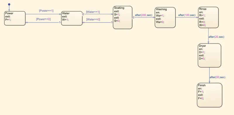
Power, Water, Soaking, Washing, Rinse, Dryer, Finish blocks added.
data given Soaking 200 sec, washing 100sec, rinsing 20 sec, drying 50sec after washing process completed.
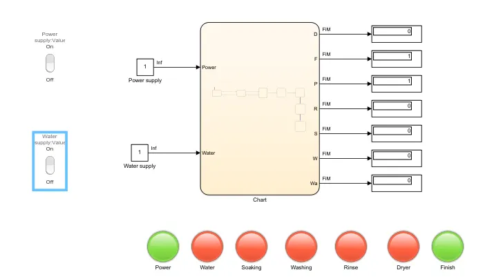
below working model.
Buttons (power & water) are connected with constant blocks. 0 indicated OFF & 1 indicated ON condition.
The lamp represents for the operation going on machine blocks.
Working:
The power Supply & water Supply will not be getting On till the Switch is Not ON physically.
Constant Blocks defined with 0 & 1 - ON & OFF condition.
After Supply gets On for both the blocks. Socking will start. After running 200sec next blocks means washing will start for 100 sec.
Completion of washing, rinse block activated, after 20-sec rinsing next dryer blocks activated and runs for 50 sec.
For above all different process different Lamp assigned which is activating with the proportional operation of specified blocks.
Problem 2: Gear shift” logic
Speed Range(kmph) Gear
0 to 15 1
16 to 25 2
26 to 40 3
41 to 60 4
Above 61 5
Below is chart prepared,

Blocks used:
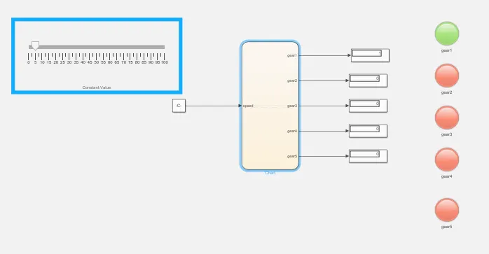
Constant- to attach slider gain.
Slider gain- to increase & decrease speed simulation
Lamp – an indication of speed is driving with gear.
State flow- Logic diagram of gear shifting.
Working:
At the starting slider gain is at 0-15KM, 1st gear activated second gear at 15-25KM, 3rd gear at 25-40KM, 4th gear ta 40-60KM, after 60Km 5th gear will show activated.
Conclusion – according to speed varies the gear shifts takes palce.