Week - 4
MAIN OBJECTIVE :
- Implement control logic of a “washing machine” using Stateflow as per given sequence:
- If the power supply is available, the system gets activated
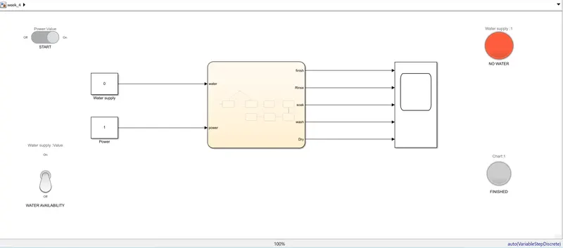
- If the Water supply is not available, stop the process & indicate through LED
- Soaking time should be 200s followed by Washing time of 100s.
- Then rinsing happens for next 20s & dryer runs for 50s
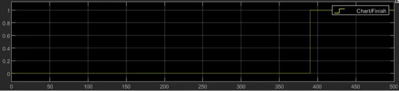
After all the processes have completed turn on the finished LED
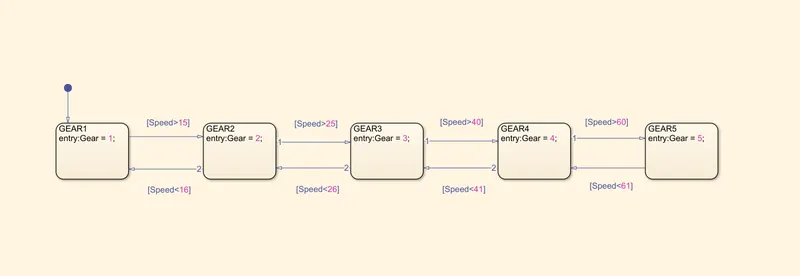
2. Make a Simulink chart for the “Gear shift” logic as per below conditions:
Speed Range(kmph) Gear
0 to 15 1
16 to 25 2
26 to 40 3
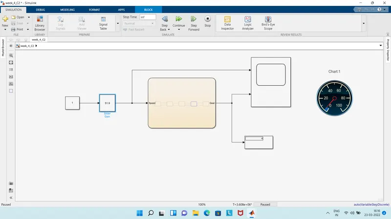
41 to 60 4
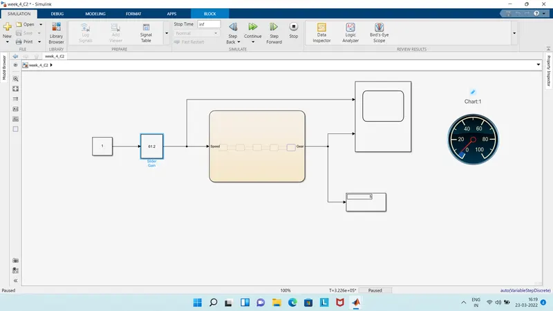
Above 61 5
Give speed input while the simulation is running & display the gear number.
OBJECTIVE - 1 :
We have to use state flow feature of the simulink to implement rthe control logic of washing machine as per the given data, Before that we need to know 2 things.
- What is state flow in simulink?
- What is washing machine?
1.A :
Stateflow provides a graphical language that includes state transition diagrams, flow charts, state transition tables, and truth tables. You can use Stateflow to describe how MATLAB algorithms and Simulink models react to input signals, events, and time-based conditions.
Stateflow enables you to design and develop supervisory control, task scheduling, fault management, communication protocols, user interfaces, and hybrid systems.
With Stateflow, you model combinatorial and sequential decision logic that can be simulated as a block within a Simulink model or executed as an object in MATLAB. Graphical animation enables you to analyze and debug your logic while it is executing. Edit-time and run-time checks ensure design consistency and completeness before implementation.
2.A :
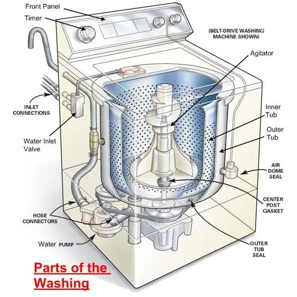
Washing machine is the machine used to wash the various types of clothes without applying any physical efforts. With washing machine you don’t have to rub the clothes with hand or squeeze them to remove the water from them. The washing machine is also called as clothes washer or simply the washer. The washing machine enables you to wash your clothes automatically without having to supervise its operation. All you have to do is put the clothes in the machine and select the wash mode. The washing machine automatically takes in the amount of water and detergent required and it also automatically sets the timer for washing, rinsing and drying as per the selected mode and the amount of clothes.
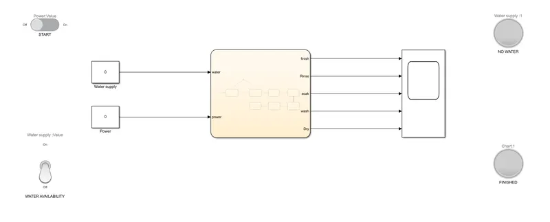
SIMULINK MODEL/STATE FLOW CHART OF CONTROL LOGIC :
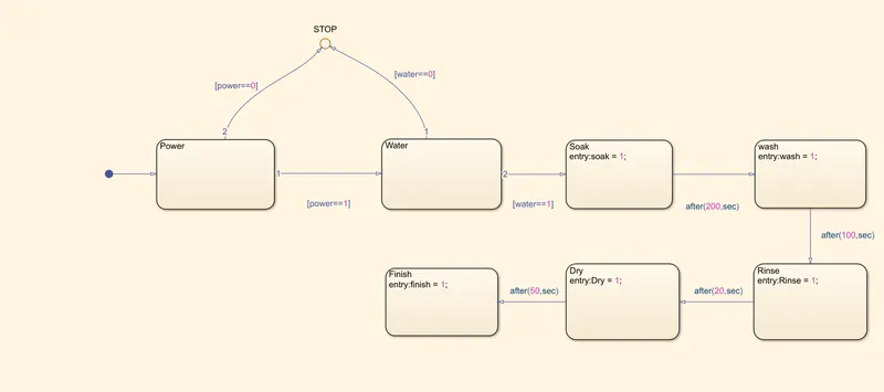
INSIDE CHART/STATEFLOW :
MODEL EXPLANATION :
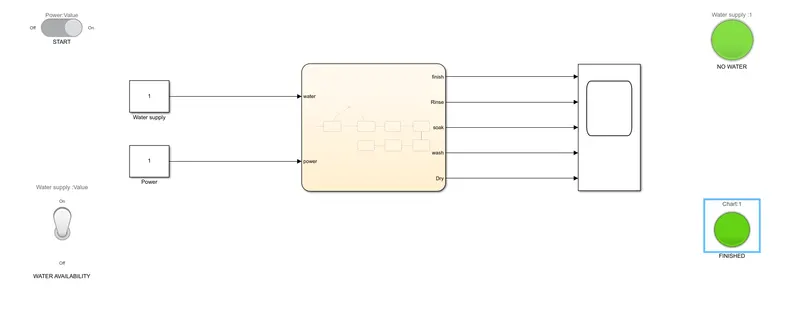
- Slide switch is used to start the process simlarily toggle switch is used to make water supply available as per our wish.
- Inside chart block bloack like structres are simply states.
- Power and water state are active when the respective switcghes on.But either of this two or both statws are inactive then signals are send to junction block to stop the process.
- Once this two state are active following operations occur in a given sequence.
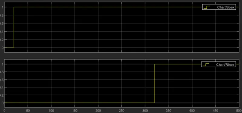
- soaking for 200s.
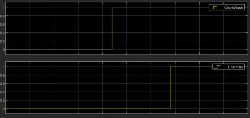
- washing for 100s.
- rinsing for20s.
- drying for 50s.
RUNNING THE MODEL WITH (NO WATER) :
RUNNING THE MODEL WITH WATER AND FINISHING THE PROCESS :
THE OUTPUT PLOTS :
OBJECTIVE - 2 :
INTRODUCTION TO GEAR TRANSMISSION SYSTEM :
The gear changing mechanism starts, quite obviously, with the gear lever. In early cars the lever ran straight down into the gearbox because the engine and gearbox were separated by a short shaft and this brought the gearbox into a convenient position for a directly-acting lever. The modern practice is to bolt these two major components together, in what became known as "unit construction". This gave greater rigidity to the transmission, as well as cutting manufacturing costs. It did mean, though, that the gearbox was mounted further forward than it used to be and this, in turn, meant that a floor-mounted lever could not be directly coupled to the gearbox. If it was it would have been extremely awkward for the driver, being either too far forward or so long that efficient, accurate changes would be difficult to achieve. The answer was to incorporate a remote control mechanism between the lever and the gearbox. Most floor-mounted, remote control mechanisms are based on a rod, though cables have been used, the rod running forward from the gear lever to the striker arm in the gearbox. This may sound simple enough but there are problems involved in this type of linkage.
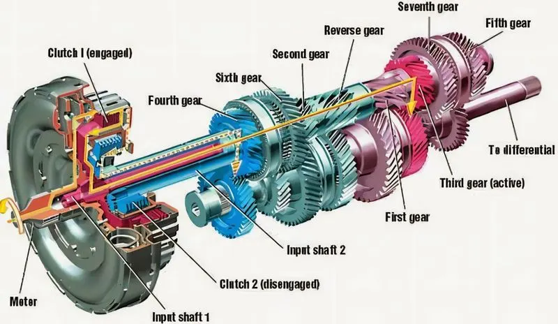
Most stem from the fact that a gear lever must move in two planes, forward and back and then from side to side to move across the gear "gate". The connecting rod must obviously be able to duplicate these movements. A rod that is simply bolted to the gear lever and striker arm could move in both directions, but its action would undoubtedly be harsh. Also, the distance between the lever and the striker arm is often around 70 cm (2ft) and a rod of this length must be supported in bearings if it is to transmit the gear lever's movements smoothly and without any flexing. Incorporating plain bearings or bushes would not affect the back and forth movement of a simple rod but they would clearly prohibit side to side action. The answer to the problem is simple. Most remote control rods are cranked at the gear lever end. This means that the sideways action of the lever is converted into rotation of the rod, an action with which the simple bearings do not interfere.
SIMULINK BLOCKS :
- CONSTANT
- SLIDER GAIN
- CHART
- DISPLAY
- SCOPE
- SPEEDOMETER
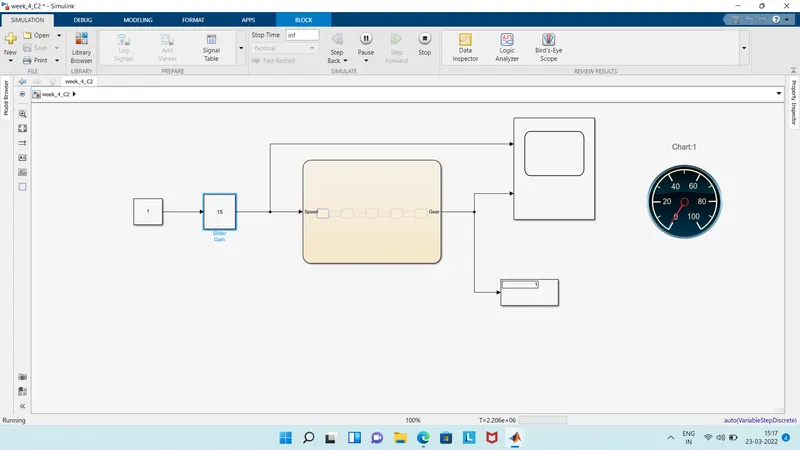
SIMULINK DIAGRAM :
- THE BLOCK DIGRAM INSIDE CHART
GEAR - 1 :
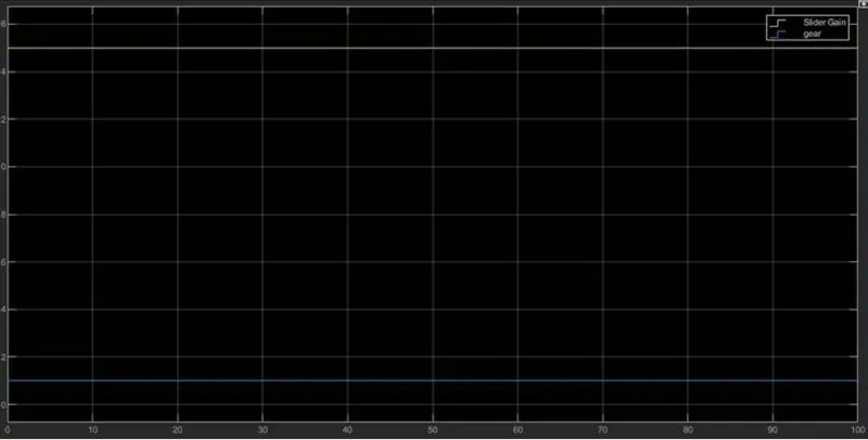
GEAR - 2 :
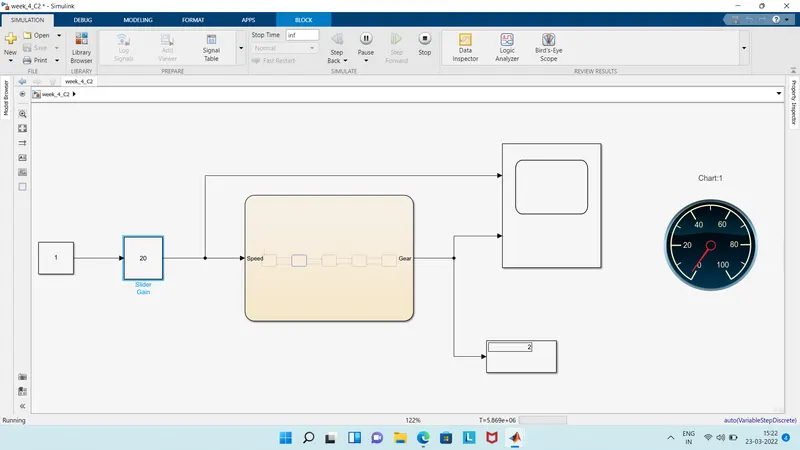
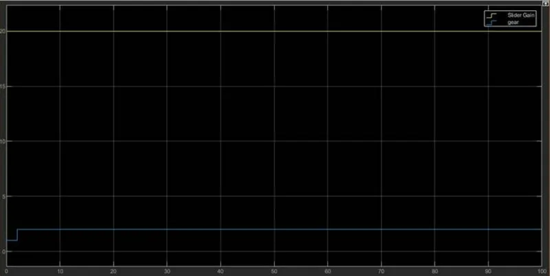
GEAR - 3 :
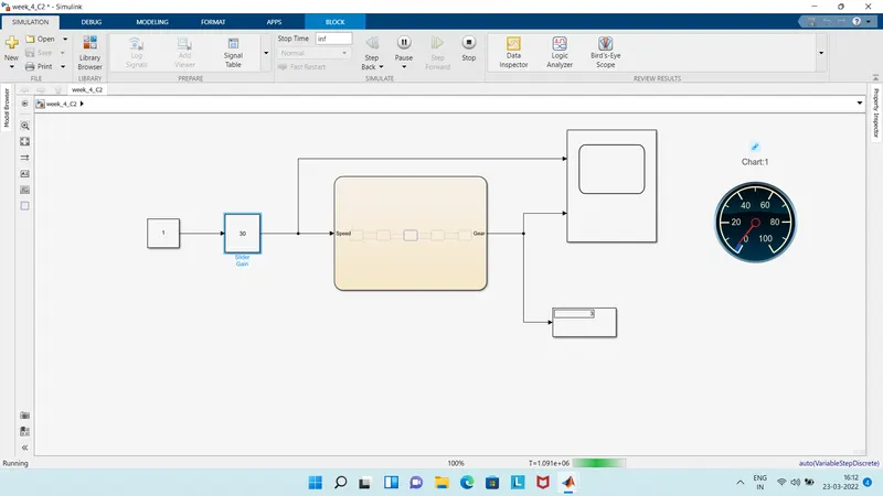
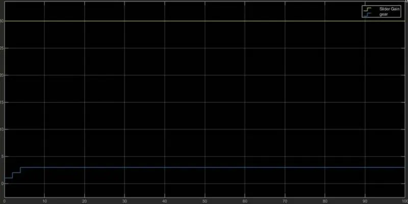
GEAR - 4 :
GEAR - 5 :
CONCLUSION :
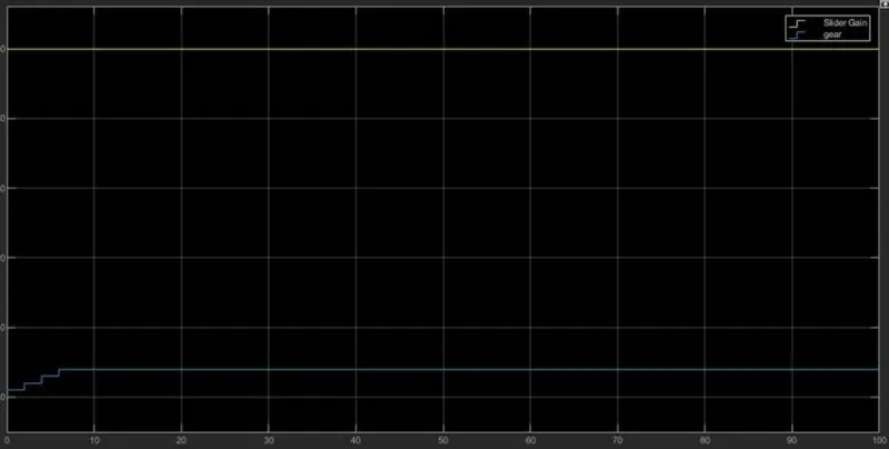
After delay of every 2 seconds, The gear shifts from one position to another position.