Week - 4
control logic of a “washing machine” using Stateflow
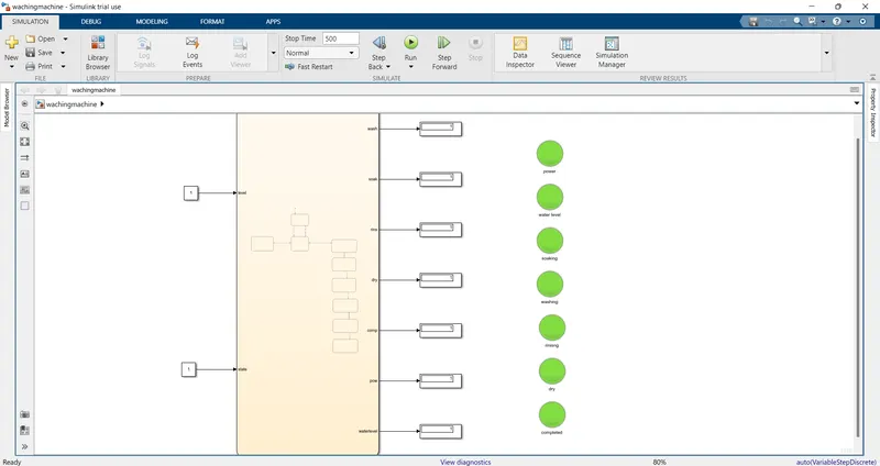
-the working stateflow simulink model SS is atteched below.
-inside the chart logics has been implemented for each state.
- the green color lamp indicates that each state has done its work.
-the SS of inside the chart posted below.
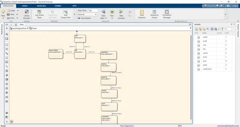
-several variable has been declared and selected their data types according to thier functionality.
Simulink chart for the “Gear shift” logic.
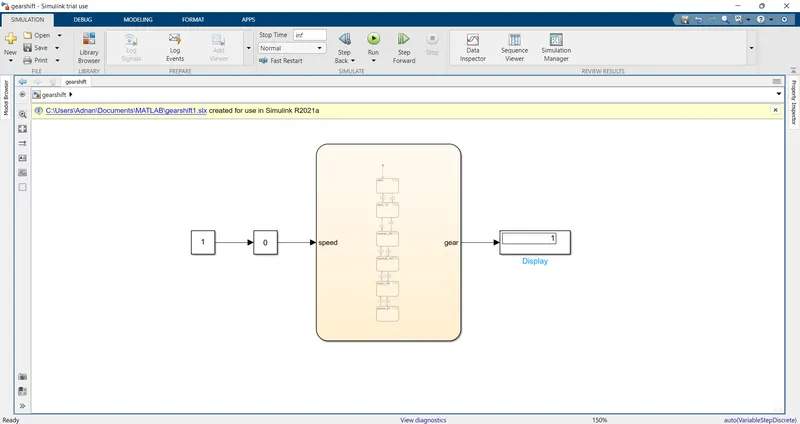
-used slider gain to give input as a speed.
-showed the gear nummber in display according to speed.
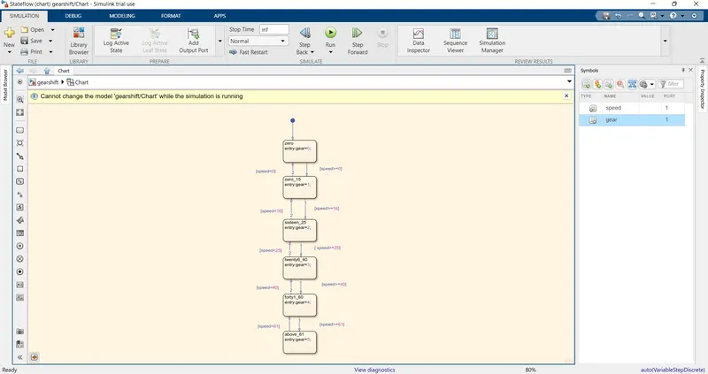
-the logic of chart is posted above.