Week - 4
Question1Implement control logic of a “washing machine” using State flow as per given sequence:
- If the power supply is available, the system gets activated
- If the Water supply is not available, stop the process & indicate through LED
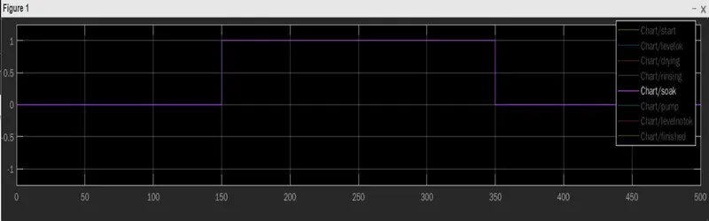
- Soaking time should be 200s followed by Washing time of 100s.
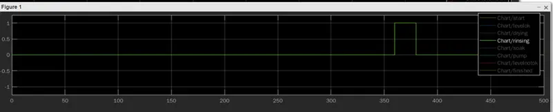
- Then rinsing happens for the next 20s & dryer runs for 50s
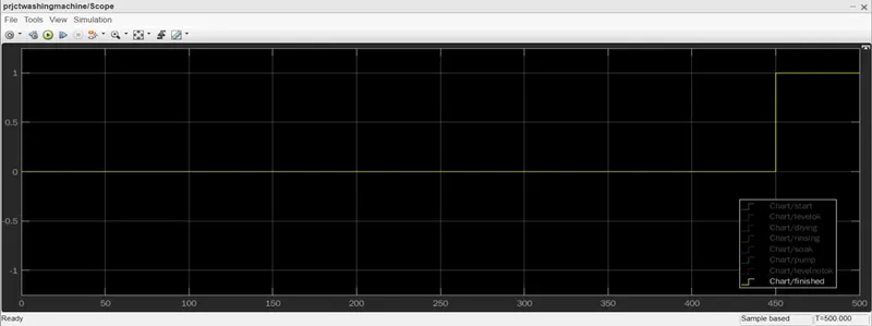
After all the processes have completed turn on the finished LED
Answer:
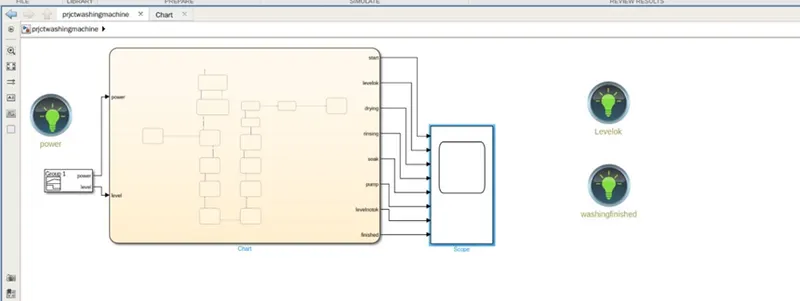
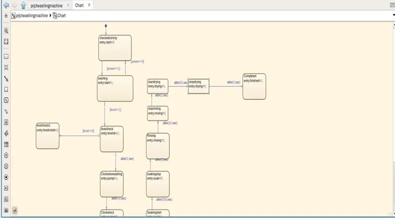
- As per above mentioned logic implemented the state flow logic for the washing machine working sequence.
- Conditions given for the running operation of the washing machine is input power should be on and the water level should be ok.
- To implement such case used signal builder and given step signal as one as the level and power ok signal to the block.
- Used LED lamps and its green indication is showing the the LED is ON or logical-1
- Please refer below mentioned logic. Indicating power, level green.
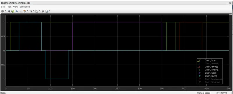
- Finished LED turned On after completion of the complete sequence please refer output trend for more clarifications
State flow chart:
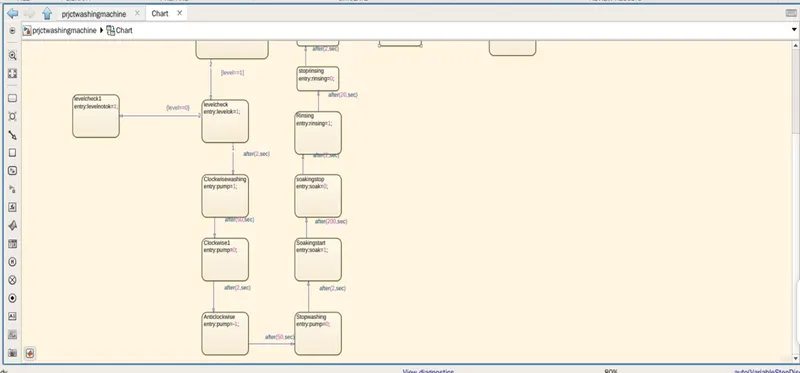
- All the conditions implemented as per the given logic.
- Also considered 2sec delay insertion between the two processed to avoid the avoid the overlapping and well running of the equipment.
Output trends:
Signals: start, drying, rinsing, soaking, pump
Pump:

Soaking:
Rinsing:
Finished:
Note: simlink slx. file not attached for the first project because it is created in the online matlab software.
all above paste images are attached as attachment also for the better visualization
Question2. Make a Simulink chart for the “Gear shift” logic as per the below conditions:
Speed Range(km/ph.) Gear
0 to 15 1
16 to 25 2
26 to 40 3
41 to 60 4
Above 61 5
Give speed input while the simulation is running & display the gear number.
Answer:
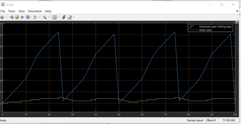
- Implemented as above mentioned logic, speed input is given from the repititive sequence from the slider gain
- i that we have geratated the different speed inputs through the diff time span and in acordence with that the gear shifting is happening.
- state flow logic is implemented and given the conditions for the automatic gear shift with respect to the given speed input.
- display and scope is used to plot the the output.
refer pic for the implemented model and also run refer attached slx. file for running actual simulation.
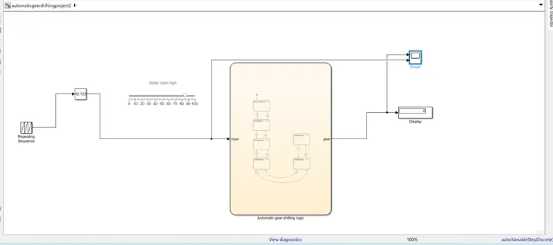
- output can generated for the the gaine values of the slider in accordance with that the gear and speed plot appearence will change: