Week -2
Project4Question:
-in arrangement when the switch is closed the electromagnet receives the electrical power from the battery it pulls the arm and hit the bell producing sound.
-Create situation where the switch is closed for the 2sec and released, observe the physical movement of the plunger.
Answer:
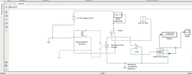
- Taken DC voltage source of 12vdc, switch which is turned ON for 2sec through the physical input.
- Used Electromagnetic converter, reluctance force actuator along with the lever mechanism.
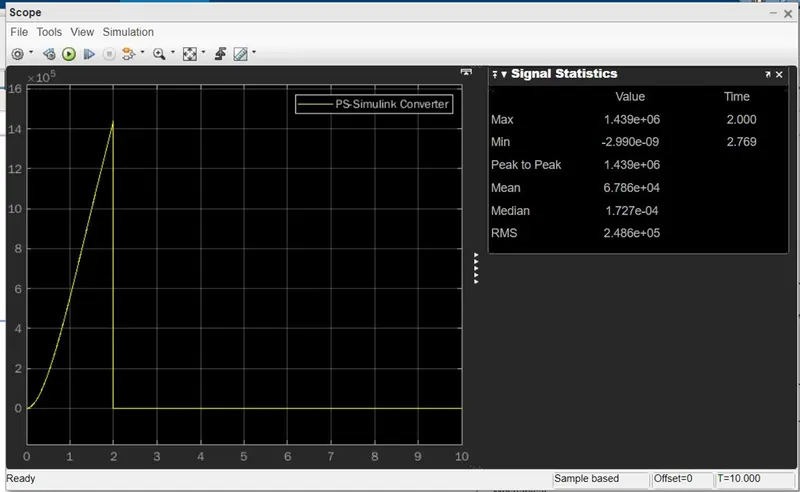
- Generated force for 2sec duration when the switch is closes is recorded.
- Solver configuration connected.
- Please refer below model and output trend.
Output plot:
Project5Question:
Use Thermistor to sense the temperature of the heater and turn ON and OFF the fan as per the below mentioned conditions.
Temperature source=
20degC- 0 to 10sec.
27degC-10 to 30sec.
23degC-30 to 50 sec
- Determined the threshold voltage value first for 25C temp value, as thermistor reading the temp in Kelvin converted 25C to its equivalent kelvin i.e 298.15K.
- Used first signal generator to generated signal for 298.15K given to Controlled temp source output controlled temp source is given to thermistor which is having NTC (negative temperature coefficient of resistivity i.e., resistance of thermistor is inversely proportional with the resistance value.
- Connected voltage source across the 200ohm resistance generated output ref temp 25C i.e., 298.15K is 2volt.
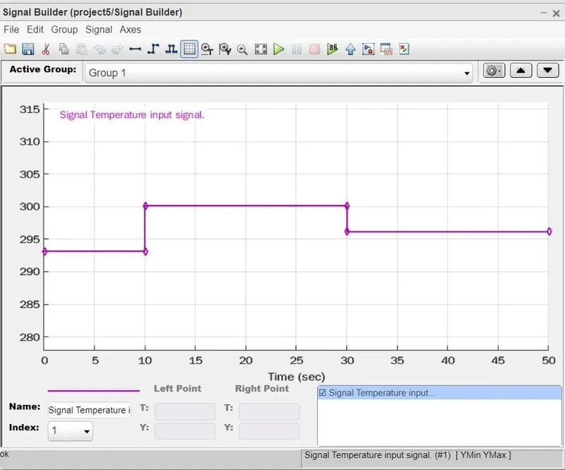
- Used another signal generator generate signal for
0 to 10sec 20C i.e., 293.15K,
10sec to 30sec 27C i.e., 300.15K
30sec to 50sec 23C i.e., 296.15K equivalent input signal as shown below.
- Used switch and implemented a condition the If input signal is greater than or equal to 2V, constants will output i.e., 1 else constant1e., 0 will be the output.
- Used differentiation of input value in PS-Simulink and Simulink-PS converter at controlled temp source and controlled voltage source. (correction done is the model because getting error to run the simulation)
- Used controlled voltage source and DC motor as to produce RPM output
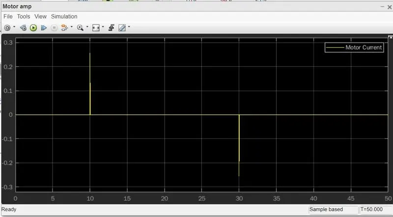
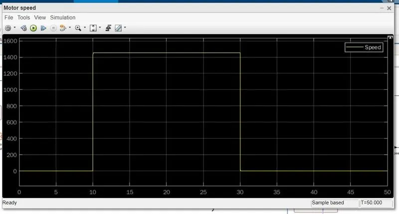
- Ideal speed sensor and current taken as output please ref output Speed of the motor and current trend shwon below.
- Simulink model for the project5 is also attached.
Motor Speed:
Motor current: