Week - 4
//QUESTION:-
- Implement control logic of a “washing machine” using Stateflow as per given sequence:
- If the power supply is available, the system gets activated
- If the Water supply is not available, stop the process & indicate through LED
- Soaking time should be 200s followed by Washing time of 100s.
- Then rinsing happens for next 20s & dryer runs for 50s ?
//ANSWER:-
1>> Simulink model with state flow chart presentation:-
>>The state flow chart :-
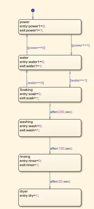
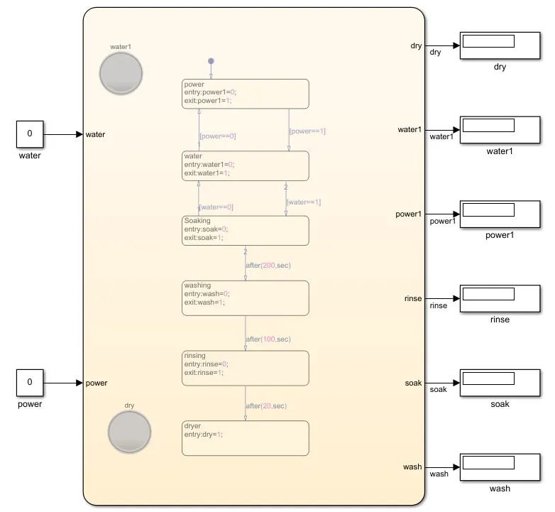
>> In the above figure shows the actual simulink model of wash and operates according to the input condition of water and power. It consist of constant,chart,and display block . In chart block the values and conditions assigned by state block and works accordingly. Here we need to achieve 4 conditions.
>power and water supply is 0, Output is 0
>power is 1 and water is 0 , Output is 0
>power is 0 and water is 1, Output is 0
For the above 3 conditions which signifies 1 as on and 0 as off, then the output obtained as 0 as per the condition which shows there is no machine operation and the output is same for all 3 conditions as shown in figure 1.
>> OUTPUT OF WASHING MACHINE:-
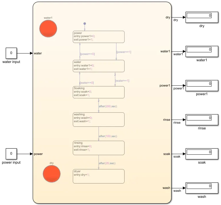
> power and water is 1 thne output is 1.
>>Red indicates OFF and GREEN indicates ON.
2// Make a Simulink chart for the “Gear shift” logic as per below conditions:
Speed Range(kmph) Gear
0 to 15 1
16 to 25 2
26 to 40 3
41 to 60 4
Above 61 5
Give speed input while the simulation is running & display the gear number.
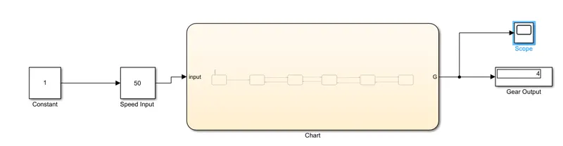
// Simulink model :-
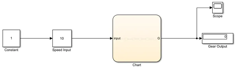
>>The flow chart

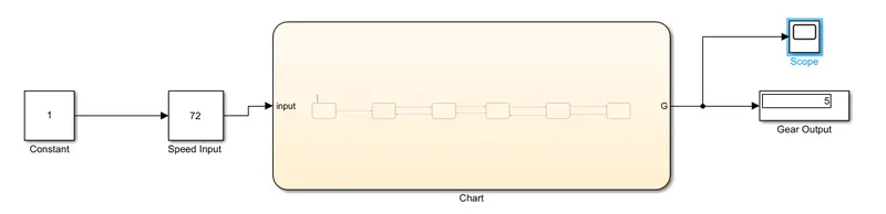
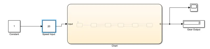
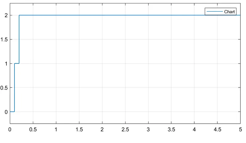
>> In the above figure shows the simulink model of gear shift using stateflow as per the input condition .The input is taken as speed which varies manually and the gear shift is obtained as per the condition.
Speed Range Gear.
0 to 15 1
16 to 25 2
26 to 40 3
41 to 60 4
above 61 5
>> Simulink block used are :-
> Constant
> Slider gain
> Chart
> Display
> Scope
>> Simulink block uses:-
> The chart block includes the value and condition as per the above formate.
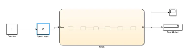
> Slider gain is used as speed which varies from 0 to 100 kmph.As the speed varies the gear shift automatically.
> Display is used for the displaying the output of the given gear shifting.
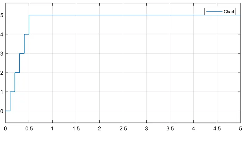
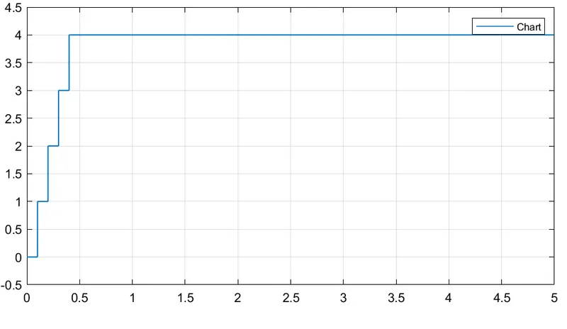
// OUTPUT OF THE SIMULINK MODEL:-
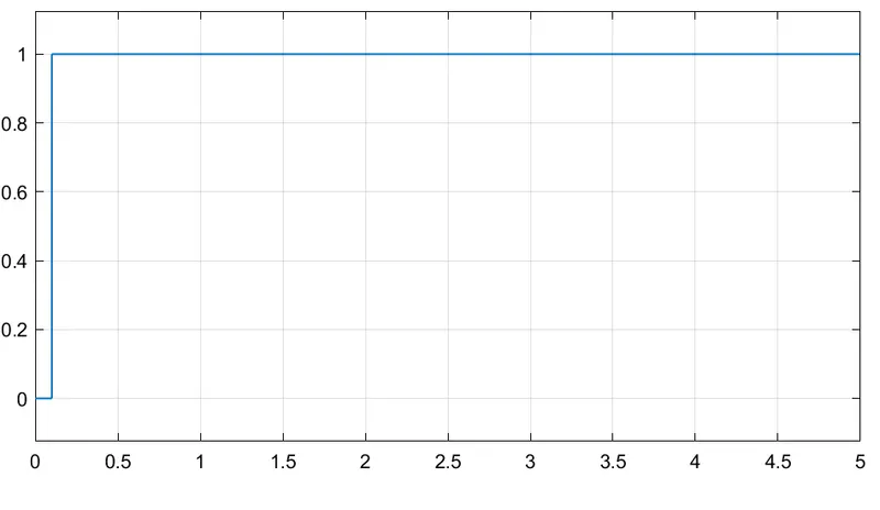
>>For gear 1.
>>For gear 2:-
>>For gear 3:-
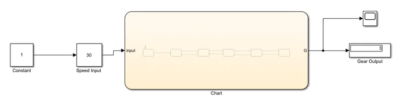
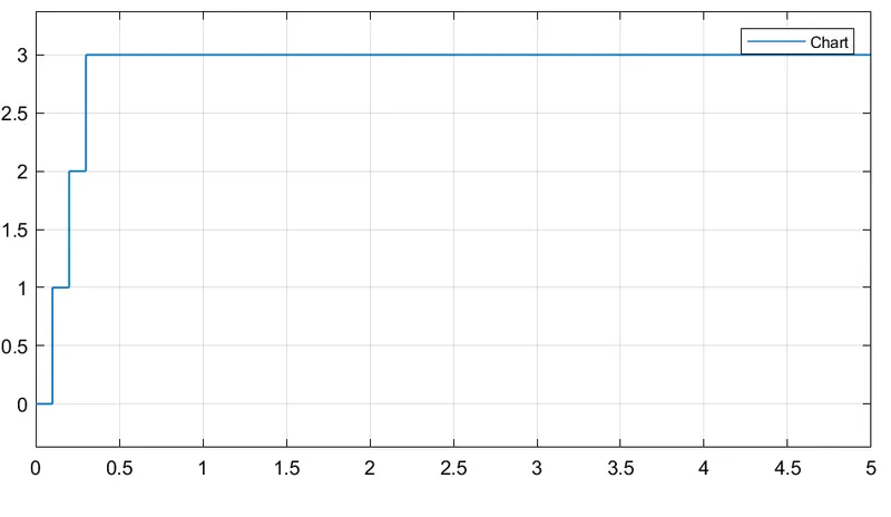
>>For gear 4:-
>>For gear 5:-