Week - 4
AIM:
- Implement control logic of a “washing machine” using Stateflow as per given sequence:
- If the power supply is available, the system gets activated
- If the Water supply is not available, stop the process & indicate through LED
- Soaking time should be 200s followed by Washing time of 100s.
- Then rinsing happens for the next 20s & dryer runs for 50s
- After all the processes have been completed turn on the finished LED
SOLUTION:
To control the washing machine we use the rocker switch on and off-state .lamps are used to indicate the on/off state of the machine. When both the power and water are on the machine starts to run or it will be in the off condition. Later on soaking, washing, rinsing, dryer starts working and after completion of given time data, the machine will stop.
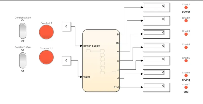
The above model show both in off condition.
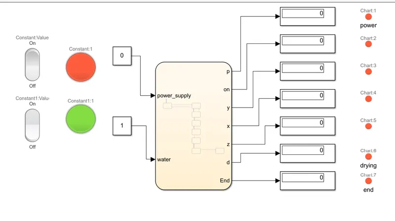
The above model show power off and water flow on.
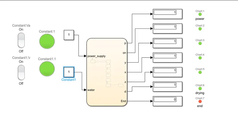
The above model shows the power and water flow are on.
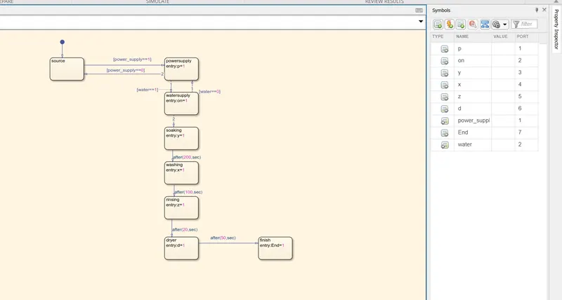
The above model indicates the working procedure of the washing machine.
The input and output ports are specified in the symbol pane.
Conclusion: The implementation of washing machine working is done using state flow.
2. Make a Simulink chart for the “Gear shift” logic as per below conditions:
Speed Range(kmph) Gear
0 to 15 1
16 to 25 2
26 to 40 3
41 to 60 4
Above 61 5
Give speed input while the simulation is running & display the gear number.
soultion
Thre given data are used to model the gear shift logic using the stateflow,The Key is used to give constant value to the slider gain which indicate the engine in on condition
Slider gain is used to increase or decrease the speed .The display is used to indicate the gear position according to speed. The below model is used to indicate gear logic.
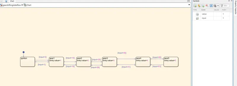
The symbols pane , input is input data and value is the output data.value is used to indicate gear postion.input is used to indicate speed.
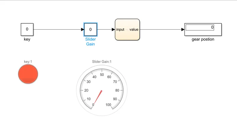
The key is in off position the output is zero in display.Lamp indicate the off condition.
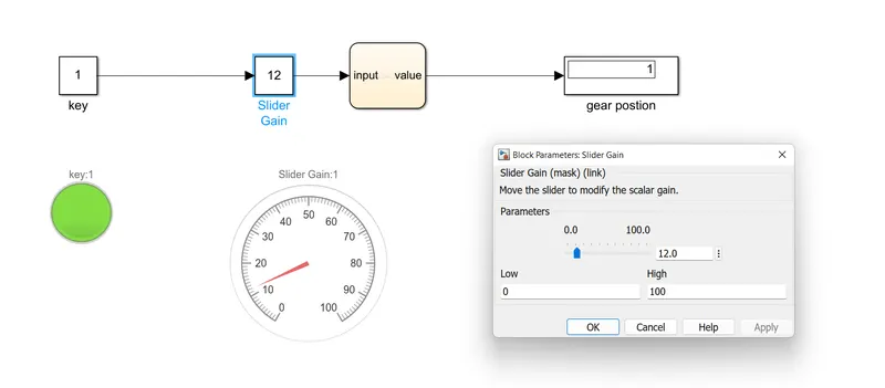
The key si in on condition lamps glows to green and the slider is in 12 indicates the speed .The output is 1 gear position.
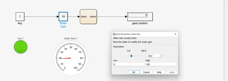
Slider is moved to 19 which has increased the speed so the gear is shifted to 2 as displayed in the gear position display.
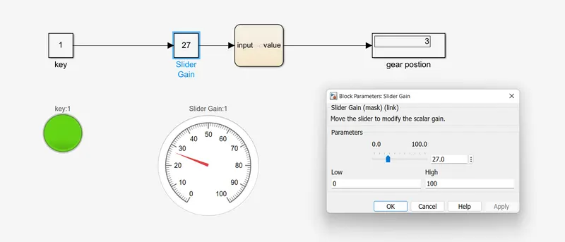
Slider is moved to 27 which has increased the speed so the gear is shifted to 3 as displayed in the gear position display.
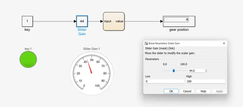
Slider is moved to 44 which has increased the speed so the gear is shifted to 4 as displayed in the gear position display.
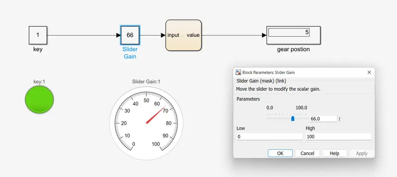
Slider is moved to 66 which has increased the speed so the gear is shifted to 5 as displayed in the gear position display
All the condition is satisfied from the given data.
Conclusion:
As speed goes on increasing the gear starts to increase and as speed starts to decrease the gear is shifted down.