Week - 4
1.
Aim:
To implement control logic of a “washing machine” using Stateflow as per given sequence
- If the power supply is available, the system gets activated
- If the Water supply is not available, stop the process & indicate through LED
- Soaking time should be 200s followed by Washing time of 100s.
- Then rinsing happens for next 20s & dryer runs for 50s
Stages with Image:
- The following control logic is implemented using Stateflow in simulink.
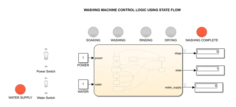
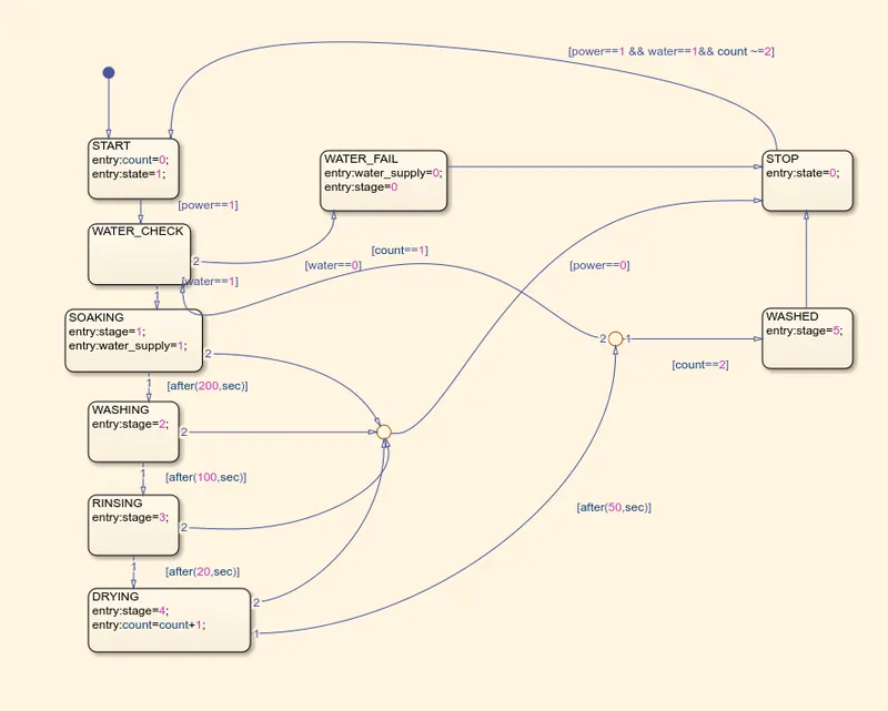
- The system has two input controls, The power and the water supply toggle switches.
- On running the simulation, it checks for the Power and Water supply availability.
- If power is not available, the system moves to the STOP state
- The water supply availability is checked before SOAKING in WATER_CHECK state and if water supply is not available, it moves to WATER_FAIL state which, on entering makes the value water_supply variable as 0 and turns the WATER SUPPLY indication to red colour.
- If water supply is available, it moves to SOAKING state and here water_supply variable is turned to 1 and WATER SUPPLY indication glows in green colour. Also the variable stage=1 here helps us to indicate which stage of washing is currently in process and thus SOAKING indicator glows.
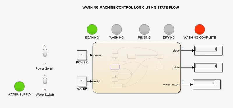
- After 200 seconds of SOAKING, the WASHING state gets activated and the status is indicated by glowing the WASHING lamp using the variable stage=2.
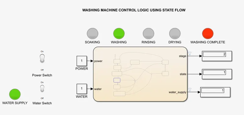
- After 100 seconds of WASHING, the RINSING state gets activated and the status is indicated by glowing the RINSING lamp using the variable stage=3
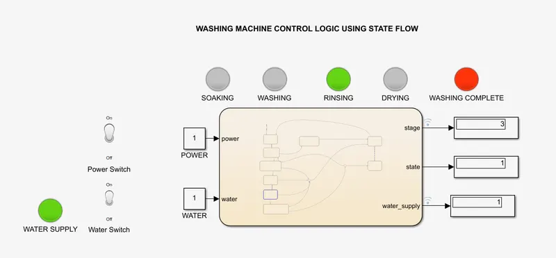
- After 20 seconds of RINSING, the DRYING state gets activated and the status is indicated by glowing the DRYING lamp using the variable stage=4.
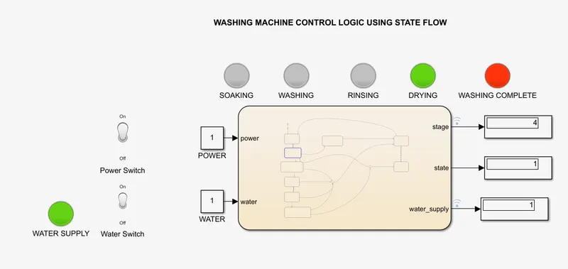
- Inorder to obtain a better washing, I have set a count variable that helps to repeat the cycle twice. Once the washing cycle is completed twice, the WASHED state gets activated which changes the variable stage=5 and glows the WASHING COMPLETE lamp.
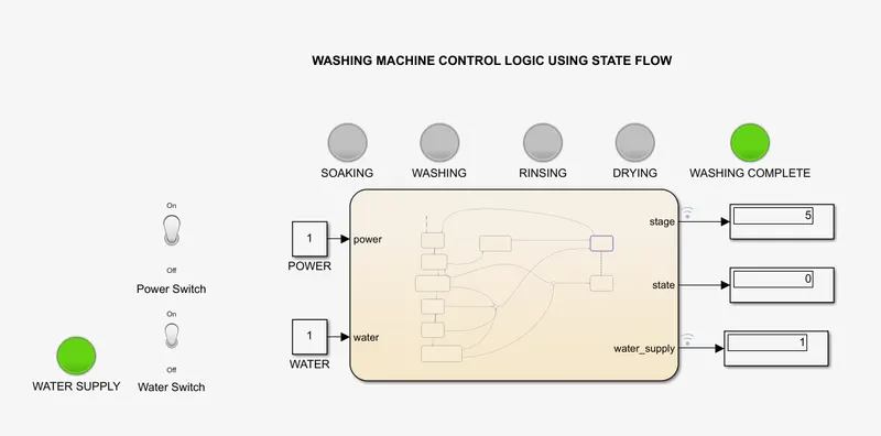
- Also during the cycle, if power fails at any state, the STOP state gets activated and will resume only if the Power and Water supply are available.
Result:
The simulation of a Washing Machine is implemented using Stateflow as described above.
---------------------------------------------------------------------------------------------------------------------------------
2.
Aim:
To make a Simulink chart for the “Gear shift” logic as per below conditions and give speed input while the simulation is running & display the gear number
- Speed Range 0 to 15 kmph : Gear 1
- Speed Range 16 to 25 kmph : Gear 2
- Speed Range 26 to 40 kmph : Gear 3
- Speed Range 41 to 60 kmph : Gear 4
- Speed Above 61 kmph : Gear 5
Stages with Images:
- Create the control logic using stateflow according to the below image.
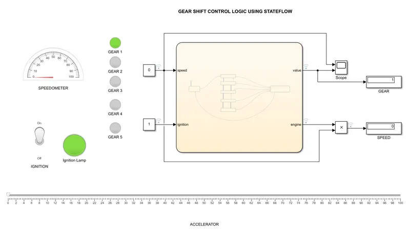
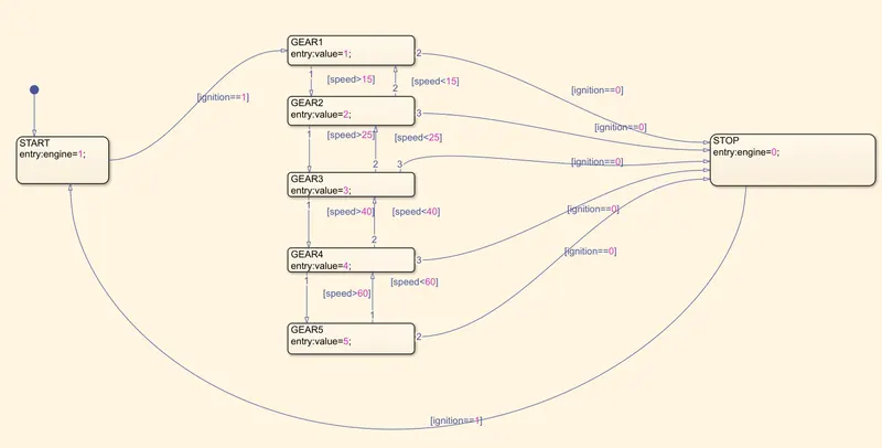
- Create the control logic using stateflow according to the below image.
- If the Ignition is ON, the GEAR1 state gets activated and variable 'value' which represents the current gear is turned to 1. The variable 'value' is set as an output and connected to a display that indicates us the the current gear. Also, indication lamps are placed for each gear and linked to 'value'.
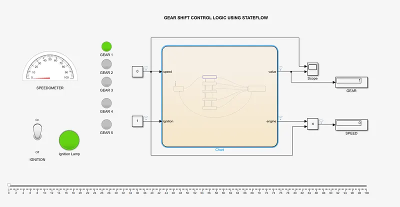
- The slider, 'ACCELERATOR' is connected to the 'speed' variable which is configured as an input. This lets us change the speed of the vehicle while running the system. Also a halfguage is configured as SPEEDOMETER to display the speed of the vehicle in the dashboard.
- On increasing the speed above 15kmph using the slider, GEAR2 gets activated seting variable value=2 and the gear is displayed as 2 and the 'GEAR 2' lamp glows.
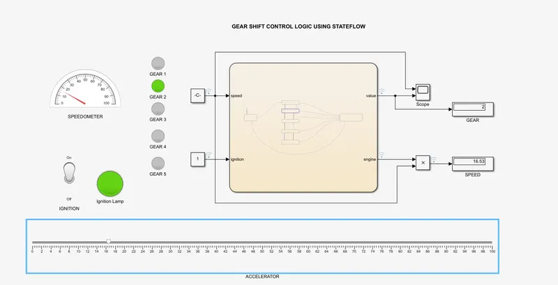
- On increasing the speed above 25kmph using the slider, GEAR3 gets activated seting variable value=3 and the gear is displayed as 3 and the 'GEAR 3' lamp glows.
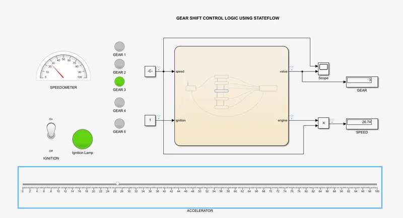
- On increasing the speed above 40kmph using the slider, GEAR4 gets activated seting variable value=4 and the gear is displayed as 4 and the 'GEAR 4' lamp glows.
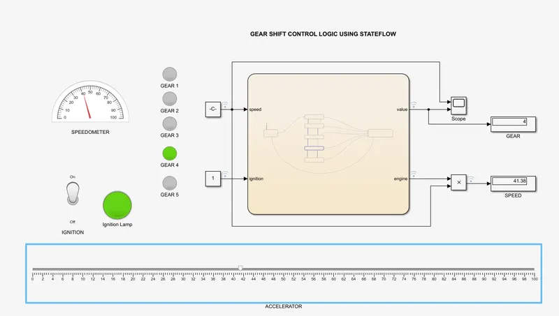
- On increasing the speed above 60kmph using the slider, GEAR5 gets activated seting variable value=5 and the gear is displayed as 5 and the 'GEAR 5' lamp glows.
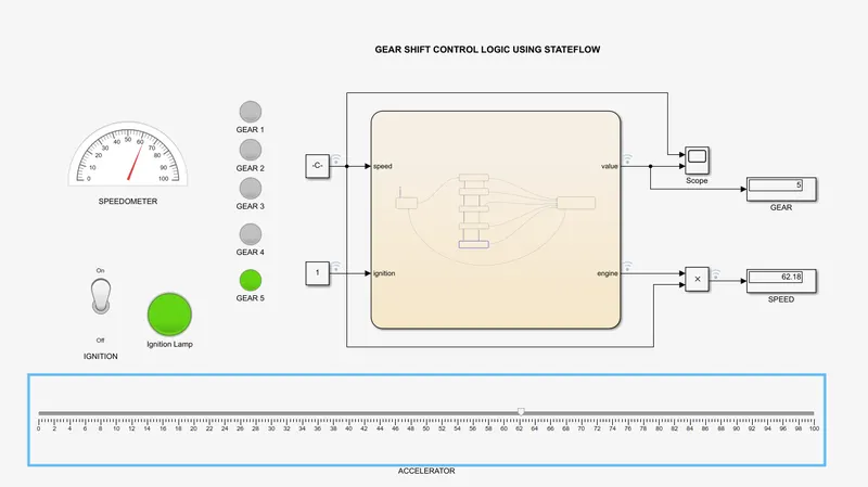
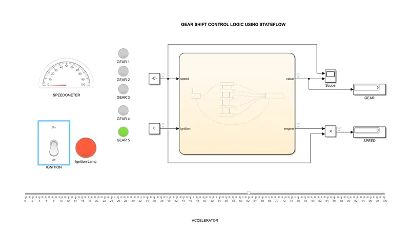
- Provision is made to switch the Gear up and down based on the speed value. Also if the Ignition switch is turned OFF, it act as an Engine Kill Switch which stops the vehicle.
Result:
The simulation of Gear Shifting based on Speed is implemented sucessfully using Stateflow as described above.