Week -2
1.
Aim: Create Simulink model of Doorbell using Solenoid block
Simulink Model:
Description:
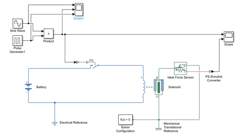
- Create the simulink block as above digram.
- The electrical part includes a battery connected to a solenoid through a switch.
- When the switch is turned on, now the current reaches solenoid and exerts a force on the solenoid.
- As we want to ring the bell, the solenoid is set as "R moves Away from C on current".
- Practically, if we place a bell to the arm R, then the Bell can ring at this point. But for a bell to ring, we need to have the arm move back and forth hitting the bell multiple times to cause the ringing effect of an electric bell.
- To have the arm move mutiple times, we need the switch to turn on and off multiple times during the time.
- For that we create a sine wave of high frequency(100 in this case) and then multiply it with a pulse generator.
- In Pulse generator, the Time period is set as 10s and the pulse width is set as 2s(20%) as we need to ring the bell for 2s.
- So effectively we have a sinewave with high frequency for 2s. Represented by the blue line in the below graph.
- To understand the motion of arm R of the solenoid, we connect it to an Ideal Force Sensor and the force output obtained is shown as the orange line in the below graph.
- This implies that the bell rings for the 2 seconds where the input signal was given to the switch.
Graph
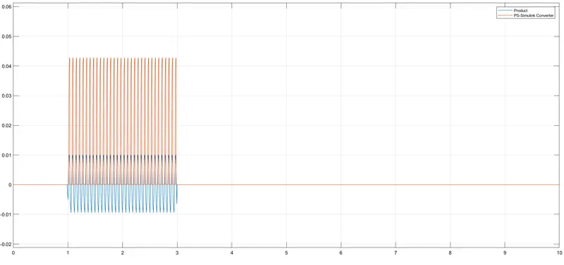
Result: A ringing effect is obtained in the bell for 2s.
2.
Aim: Use a thermistor to sense temperature of a heater and turn on the fan if the temperature goes above 25 degC and turn off the fan when the temperature falls below 25 degC. The temperature source should give 20 °C from 0 to 10 seconds, 27 °C from 10 to 30 seconds, 23 °C from 30 to 50 seconds.
Simulink Model: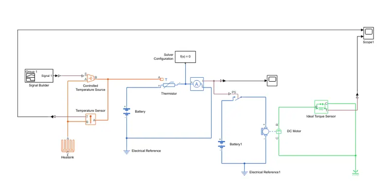
Description
- Create the simulink model according to the above diagram
- Use a signal builder to control the Controlled Temperature source in order to obtain the required temperature (20 °C from 0 to 10 seconds, 27 °C from 10 to 30 seconds, 23 °C from 30 to 50 seconds).
- The temperature is fed to a thermistor whose resistance changes with the temperature.(Resistance increases with the temperature). Therefore the current through the circuit decreases with increase in temperature.
- Use a current sensor to measure the current and its output is fed to a switch in the fan circuit.
- The treshhold value of the switch is set as 0.032A which curresponds to the current at 25deg C.
- Thus as the temperature crosses 25degC, the treshhold value in the switch gets crossed and switch is turned on and current reaches the fan(represented by a DC motor here).
- The switching ON and OFF of the fan is captured by an Ideal Torque Sensor and following output is optained in the scope.
Graph:
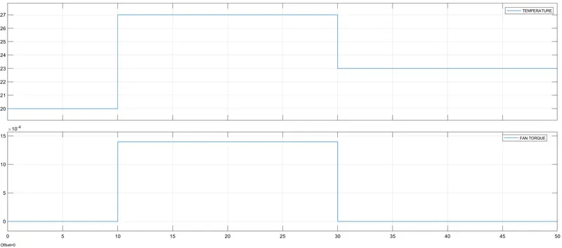
Result: The fan turns on as the temperature goes above 25degC and turns off as the temperature comes below 25degC.