Week - 4
Control Logic Of washing Machine and Gear Shift using Stateflow in SIMULINK
Aim :-
1.Implement control logic of a washing machine using stateflow buy using given conditions.
- Create the state flow for gear shift and very the speed as input and obtain the output as the gear number in display.
State flow ;-Stateflow provides a graphical language that includes state transition diagrams, flowcharts are state transition tables. By using state flow to describe how matlab algorithms and Simulink models react to input signals, events,and time -based conditions.
Control logic – control logic is a model system logic of a washing machine using state flow
Objective –
1.Implement control logic of a washing machine using state flow.
Given sequence ;-
If the power supply is available, the system gets activated
If the Water supply is not available, stop the process & indicate through LED
Soaking time should be 200s followed by Washing time of 100s.
Then rinsing happens for next 20s & dryer runs for 50s.
Soaking -
Soak Function is used to dip clothes in detergent water to remove dirt from the clothes.
Firstly, pulsator will rotate for 1 min and then next 4 min machine will be at rest position then again it will rotate for a minute. This function will be repeated throughout the time which was selected by customer for soak.
Washing –
During the wash cycle, large plastics alligator turns around, moving your clothes through the water. When the wash is finished, the pump drains the water from the outer drum.
Rinse:
The dirty, soapy water is drained, then the washing machine is refilled and your clothes are "rewashed" in clean water. Spin: All the water is drained completely, then your clothes are spun very fast and excess water is removed thanks to centrifugal force.
Dryer -
They work by pushing warm dry air through your washing to extract moisture, then cooling the now humid air in a heat exchanger to condense the moiture, which is collected in a tank or pumped down the drain. The air is reheated and the cycle repeats.
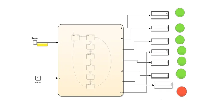
Whashing Machine Model -
State Flow Logic :-
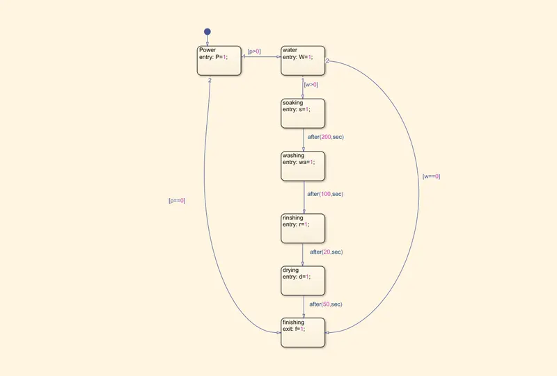
Procedure-
For making the model we have to create a stateflow chart with power, water, soaking , washing ,rinsing ,Dry and finsh of the cycle.
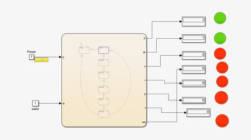
The power and wate supply to the machine are dependent upon the switch conditions which is on or off as defined by the constant value 0 or 1.
The signal with the given state flow logic.If the value displayed is 1 then the power and the water supply to the machine.
If the value is 0 and 1 then the machine will not start the process as one of the switches is off.
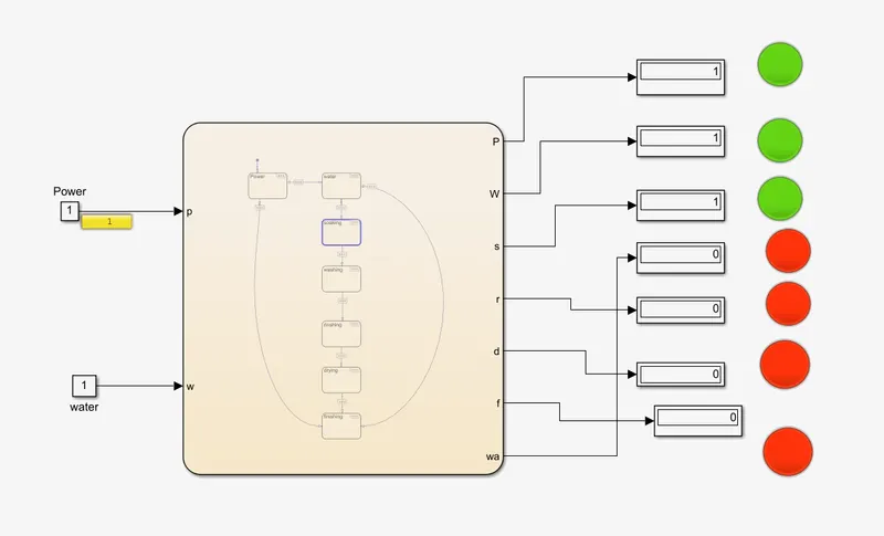
When the both power and water at 1 then the shocking process starts and run for 200sec after this washing started, this process is running in 100 sec.
After 100sec the rinshing process starts, after completion of rinshing time 20sec, drying process is started this process is done in 50 sec, at the time of drying water supply is cut off.
After completion of all the processes , the machine has turn off.
Power and Water Supply-
shocking -
Washing -
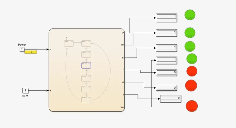
Rinshing-
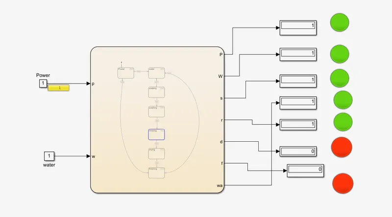
Drying and Finish -:-
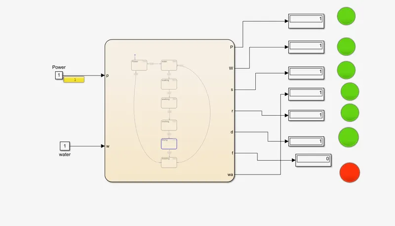
Gear shift control logic-
Given -
Make a Simulink chart for the “Gear shift” logic as per below conditions:
Speed Range(kmph) Gear
0 to 15 1
16 to 25 2
26 to 40 3
41 to 60 4
Above 61 5
Give speed input while the simulation is running & display the gear number.
Gear Shift Model -
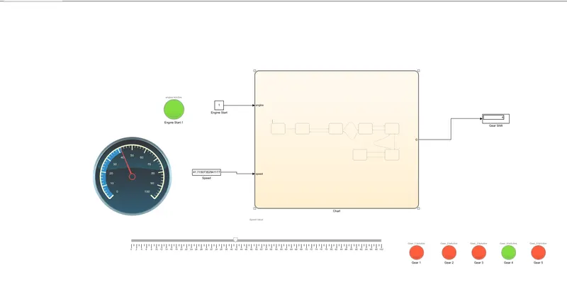
State Flow Logic-
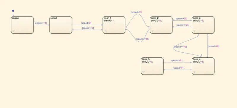
Blocks used in the model -
Constant- To multiply with the slider gain.
Slider gain – It acts as a throttle to increasing or decrease the speed.
Lamp – For indicating the gear number.
State flow -control logic of gear shifting.
Custom gauge – It’s working as the speedometer of the vehicale means to show the speed of the vehicle.
when Engine off -
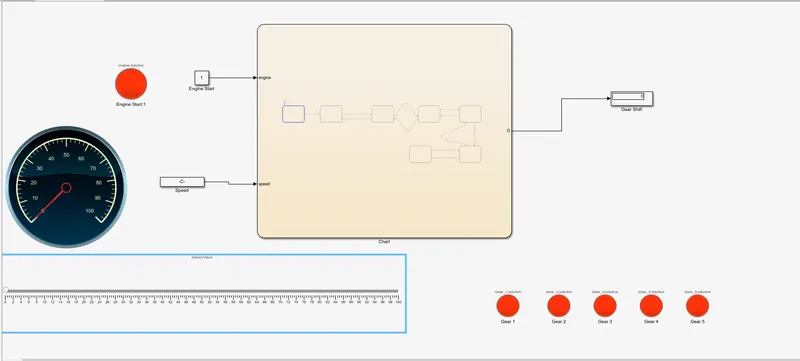
Engine On-
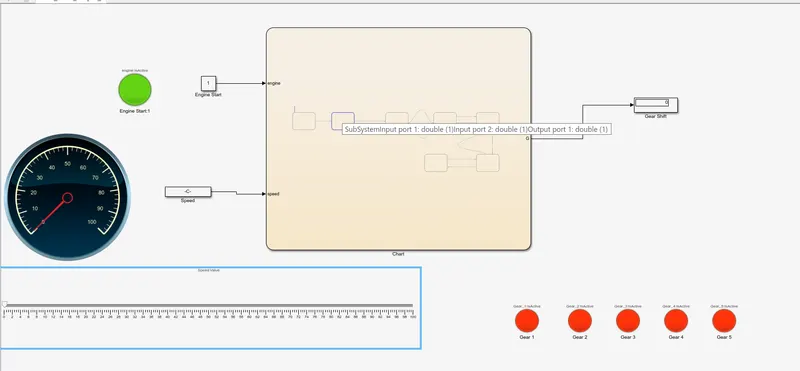
Gear -1
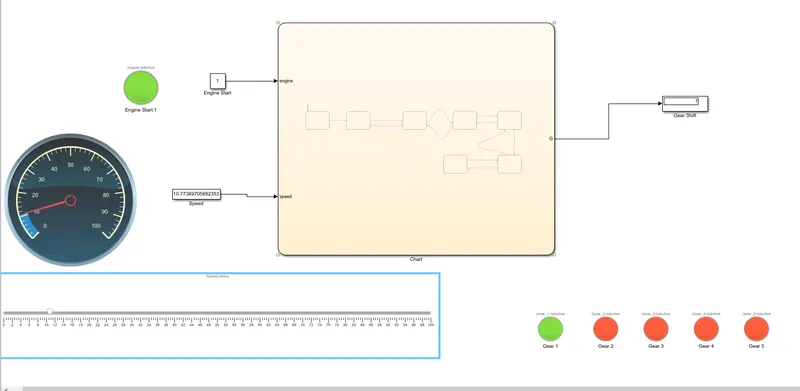
Gear -2
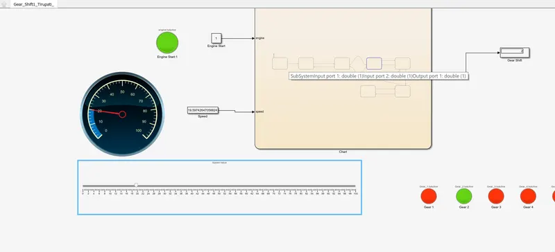
Gear -3
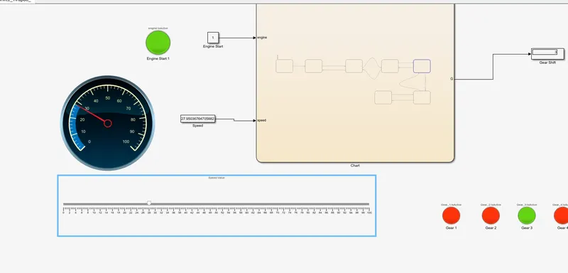
Gear -4
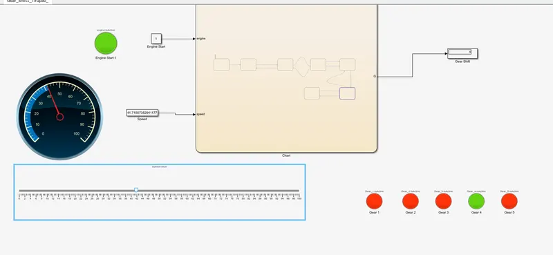
Gear -5
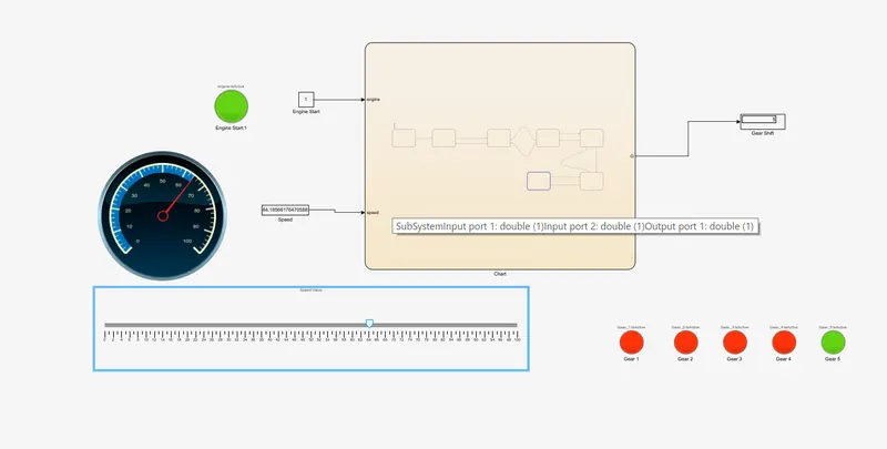
Conclusion :-Thus the control logic of a Washing machine and Gear Shift Simulink chart had compleated.