Week - 4
- Implement control logic of a “washing machine” using Stateflow as per given sequence:
- If the power supply is available, the system gets activated
- If the Water supply is not available, stop the process & indicate through LED
- Soaking time should be 200s followed by Washing time of 100s.
- Then rinsing happens for next 20s & dryer runs for 50s
After all the processes have completed turn on the finished LED
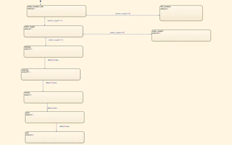
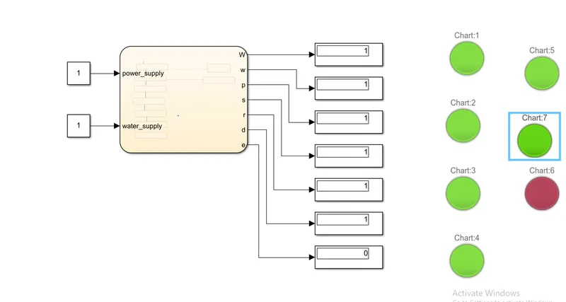
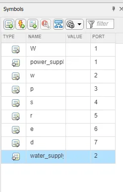
so from the above char we have taken flow chart and given the connection from power on to end .
And we have given given lamps for the light indicator.
And also we have given the output and input directions as well as values.
After giving constant and dispaly option to every block we can we see thr result as well lamps turing into its color.
This is how the washing machine state flow is desinged.
--------------------------------------------------------------------------------------------------------------------------------------------------------------------------------------------------------------------------------------------------------------------------------------------------
2. Make a Simulink chart for the “Gear shift” logic as per below conditions:
Speed Range(kmph) Gear
0 to 15 1
16 to 25 2
26 to 40 3
41 to 60 4
Above 61 5
Give speed input while the simulation is running & display the gear number.
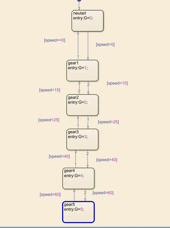
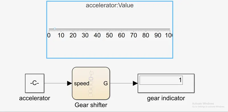
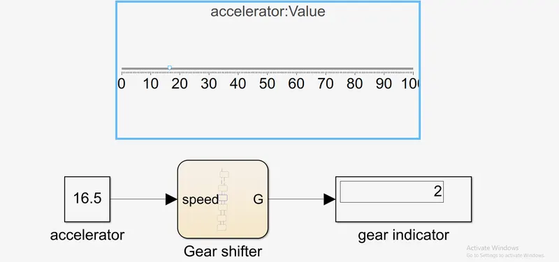
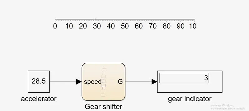
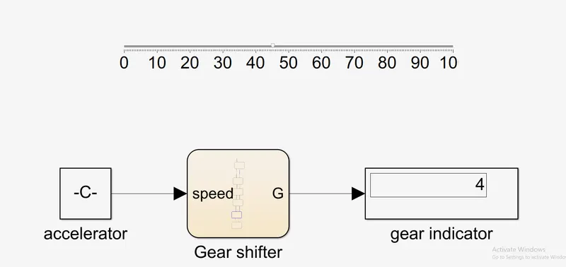
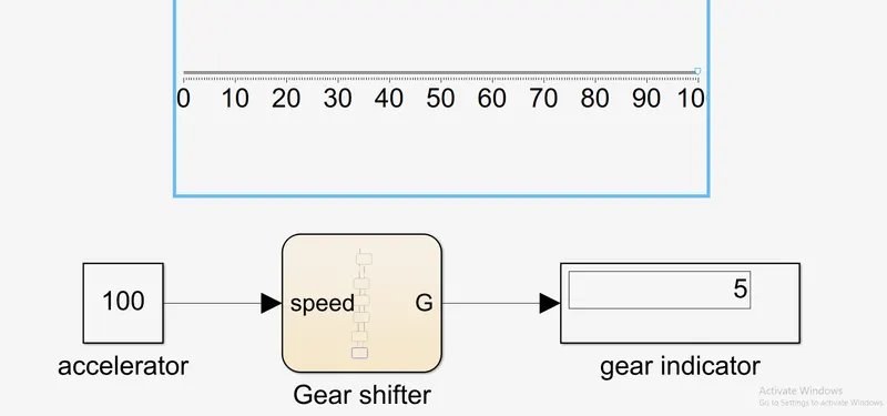
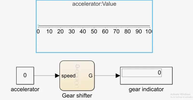
so from the above desgin we can see how the gear is changed when the accelarator value is changed.
For every change in accelartion the accelerator value is also changed clearly.
And in the flow chart from the nuetral to gear fifth we have designed the cnnections.
This is how the gear shift is seen and calculated .
------------------------------------------------------------------------------------------------------------------------------------------------------------------------------------------------------------------------------------------------------------------------------------