Photo Realistic Rendering
Title: Modeling, Assembly & Photorealistic Rendering of American Chopper.
Objective:
To model parts of the American Chopper Bike using solidworks . Later
assemble all the parts together, give the proper appearance (color & material) to the parts,
adding decals, set up cameras, lights & environment, etc. In the end, render realistic photos of
the bike using solidworks Visualize.
Introduction:
This report is about 3D modeling of the American Chopper Bike using
solidworks. solidworks is a 3D CAD software that is used to create 3D CAD
models of different types of products which consist of solid modeling, Surfacing, Sheet
Metal, Weldments, etc. The modeling of different parts of the bike is done using various
features and given an appropriate appearance individually. Later all the parts are assembled
together using proper mates. Then the assembly is rendered with realistic environment.
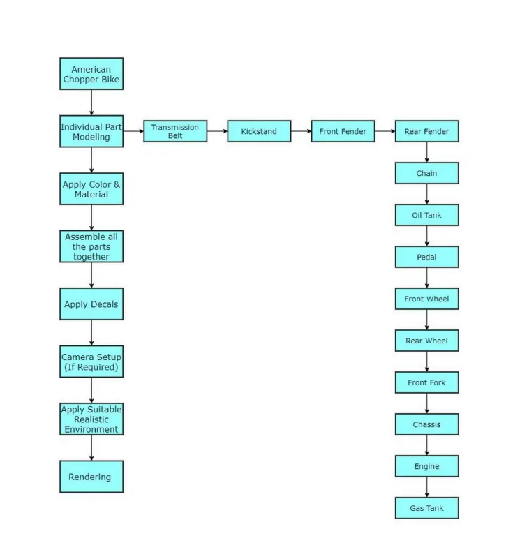
Design Methodology/Approach: It is explained by the following flowchart
Description:
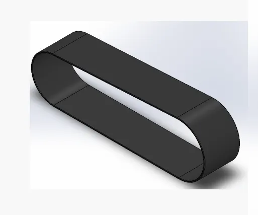
1. Transmission Belt:
A Transmission belt is used to transmit the power. In bikes, it is used
to transmit power from the engine to the rear wheel.
Following are the tools and features used while designing:-
• Sketch
• Circles
• Lines
• Offset
• Constrains (Tangent, Horizontal, Coincident, etc)
• Boss Extrude
• Fillet
2. Kickstand:
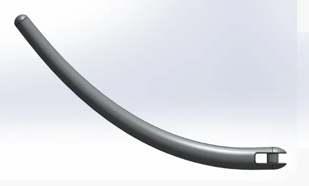
Kickstand also known as Sidestand. It keeps the bike upright while the bike is
at rest.
Following are the tools and features used while designing:-
• Sketch
• Circle
• Line
• Elipse
• Rectangle
• Spline
• Constrains (Pierce, Horizontal, Coincident, Vertical, Midpoint, etc)
• Plane
• Loft
• Dome
• Cut Extrude
• Split
• Boss Extrude
• Fillet
3. Front Fender:
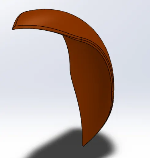
Its primary function is to protect the Rider, Engine Block, and other parts
from Sand, Mud, Rocks, Liquids, and other road sprays which are thrown into the air by
rotating tire due to centrifugal force.
Following are the tools and features used while designing:-
• Sketch
• Circle
• Line
• Spline
• Constrains (Horizontal, Coincident, Vertical, Midpoint, Symmetric, etc)
• Revolve
• Split
• Fillet
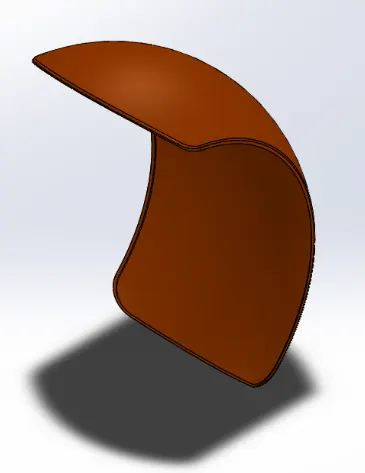
4. Rear Fender:
Its primary function is to protect the Rider, Engine Block, and other parts
from Sand, Mud, Rocks, Liquids, and other road sprays which are thrown into the air by
rotating tire due to centrifugal force.
Following are the tools and features used while designing:-
• Sketch
• Circle
• Line
• Constrains (Horizontal, Coincident, Vertical, Midpoint, etc)
• Revolve
• Split
• Fillet
• Shell
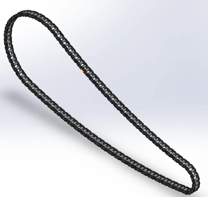
5. Chain:
Chain Transmits the motion from the gearbox to the rear wheel sprocket.
Following are the tools and features used while designing:-
• Sketch
• Circle
• Line
• Blocks
• Spline
• Constrains (Pierce, Horizontal, Vertical, Tangent, Coincident, Midpoint, etc)
• Curve Driven Pattern
• Cut Extrude
• Delete Body
• Boss Extrude
• Fillet
• Mirror
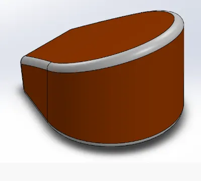
6. Oil Tank:
The oil tank stores lubricating oil for the Engine. For smooth and efficient
running the engine requires lubrication. The oil tank supplies lubrication oil to the engine and
other parts of the bike.
Following are the tools and features used while designing:-
• Sketch
• Circle
• Line
• Spline
• Constrains (Horizontal, Vertical, Tangent, Coincident, Midpoint, Symmetric, etc)
• Boss Extrude
• Fillet
• Combine
• Shell
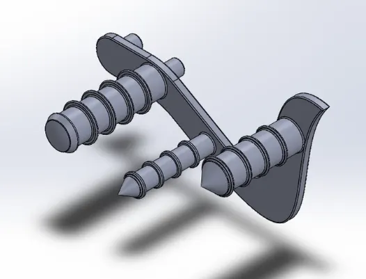
7. Pedal:
The bike rider rests their feet on the pedal while ridding and also controls the Gear
& Rear Brake.
Following are the tools and features used while designing:-
• Sketch
• Circle
• Line
• Spline
• Constrains (Horizontal, Vertical, Tangent, Coincident, Parallel, Equal, Symmetric,
etc)
• Boss Extrude
• Fillet
• Revolve
• Dome
• Chamfer
• Linear Pattern
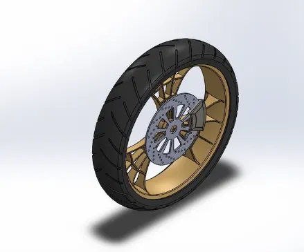
8. Front Wheel:
The front is a freewheel that is mounted to the Front Fork. In this bike, the
front wheel consists of Tyre, Alloy Rim, and Disk Brake.
Following are the tools and features used while designing:-
• Sketch
• Circle
• Line
• Spline
• Arc
• Offset
• Convert Entities
• Constrains (Horizontal, Vertical, Tangent, Coincident, Parallel, Equal, Symmetric,
etc)
• Boss Extrude
• Fillet
• Revolve
• Revolve Cut
• Circular Pattern
• Extrude Cut
• Combine
9. Rear Wheel:
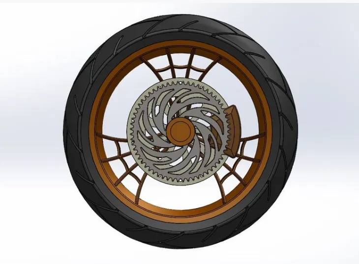
The Rear is a driving wheel that is mounted to the Chassis. In this bike, the
front wheel consists of Tyre, Alloy Rim, Sprocket, and Disk Brake. The Chain from the
engine is connected to the sprocket of the wheel.
Following are the tools and features used while designing:-
• Sketch
• Circle
• Line
• Spline
• Arc
• Offset
• Convert Entities
• Constrains (Horizontal, Vertical, Tangent, Coincident, Parallel, Equal, Symmetric,
etc)
• Boss Extrude
• Fillet
• Revolve
• Revolve Cut
• Circular Pattern
• Extrude Cut
• Combine
10. Front Fork:
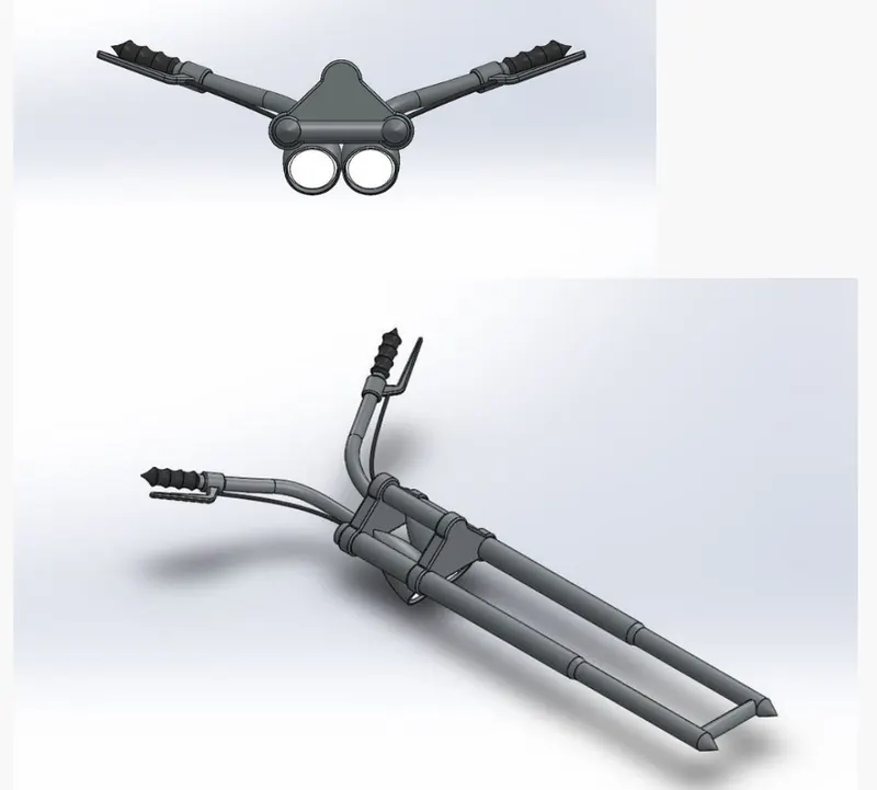
Front Fork gives the desired direction to the bike. It is connected to the
Chassis and Front Wheel is connected to the fork. The Handgrip, brake & Clutch is
connected to the Handle which is also connected to the Front Fork.
Following are the tools and features used while designing:-
• Sketch
• Circle
• Line
• Spline
• Arc
• Offset
• Convert Entities
• Plane
• Constrains (Horizontal, Vertical, Tangent, Coincident, Parallel, Equal, Symmetric,
etc)
• Boss Extrude
• Fillet
• Revolve
• Revolve Cut
• Linear Pattern
• Extrude Cut
• Combine
• Sweep
• Move Body
• Project Curve
• Mirror
11. Chassis:
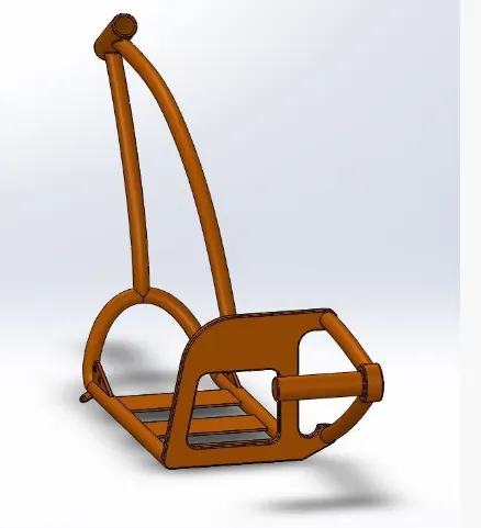
The chassis is the main part of the bike. All the parts of the bike are mounted on
the chassis.
Following are the tools and features used while designing:-
• Sketch
• Sketch Picture (BluePrint)
• Circle
• Line
• Spline
• Arc
• Offset
• Convert Entities
• Plane
• Constrains (Horizontal, Vertical, Tangent, Coincident, Parallel, Equal, Pierce, etc)
• Boss Extrude
• Fillet
• Revolve
• Extrude Cut
• Combine
• Sweep
• Split
• Project Curve
• Mirror
• Dome
• Chamfer
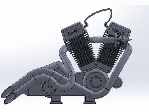
12. Engine:
The engine is the heart of the bike. It contains Gear Box, Piston Cylinders,
Exhaust Pipes, and Spark Plugs. The engine is mounted on the Chassis.
Following are the tools and features used while designing:-
• Sketch
• Sketch Picture (BluePrint)
• Circle
• Line
• Spline
• Arc
• Offset
• Convert Entities
• Plane
• Constrains (Horizontal, Vertical, Tangent, Coincident, Equal, Pierce, etc)
• Boss Extrude
• Fillet
• Revolve
• Extrude Cut
• Circular Pattern
• Linear Pattern
• Mirror
• Combine
• Sweep
• Split
• Project Curve
• Mirror
• Dome
• Composite Curve
• Chamfer
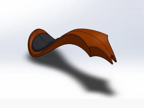
13. Gas Tank:
Gas Tank stores the fuel and supplies it to the engine.
Following are the tools and features used while designing:-
• Sketch
• Sketch Picture (BluePrint)
• Circle
• Line
• Spline
• Offset
• Plane
• Constrains (Horizontal, Vertical, Tangent, Coincident, Pierce, etc)
• Surface Sweep
• Fillet
• Swept Cut
• Surface Trim
• Boundary Surface
• Split Line
• Surface Extrude
• Surface Loft
• Project Curve
• Surface Knit
• Composite Curve
• Shell
• Mirror
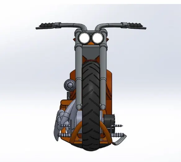
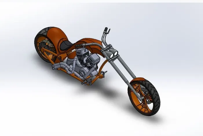
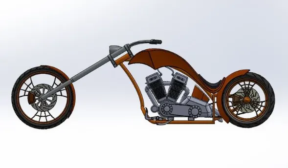
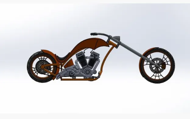
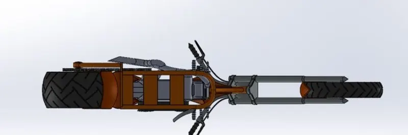
Assembly of American Chopper Bike
After modeling all the parts individually, all the parts are assembled together using
appropriate mates.
Following are the different mates which are used for assembly:-
• Coincident Mate
• Distance Mate
• Concentric Mate
• Limit Angle Mate
• Width Mate
• Angle Mate
• Parallel Mate
• Tangent Mate
Conclusion:
The design of the American Chopper Bike helped to understand various tools of
solidworks. We got to learn about Solid Modeling, Surfacing, how to handle splines,
and many more other things. We have also learned about various mates used in the assembly
of the bike and later render the assembled bike with appropriate Color, Materials, Decals,
Environment, Lighting, Camera Setup, etc.