Week - 4
Q1)Implement control logic of a “washing machine” using Stateflow as per given sequence:
- If the power supply is available, the system gets activated
- If the Water supply is not available, stop the process & indicate through LED
- Soaking time should be 200s followed by Washing time of 100s.
- Then rinsing happens for next 20s & dryer runs for 50s
After all the processes have completed turn on the finished LED
Ans. The different operations of a system are controlled via what is called a control logic. The input is fed by the user, to which the control logic responds by performing the automated tasks.
State is the operating mode of a system, stateflow is a graphical representation made up of states and transitions from one state to another forming a sequential logic system. The transition in different states is decided by the user's input.
Working principle of a washing machine
A washing machine spins at 1000-1500 rpm helps soap along with dirt to leave the surface of the cloth via centrifugal force and into outlet pipes. The processes are electrically controlled, such as the drum, valves, pump and the motor.
The valves opens to let the dirty water drain out of the drums, The pump's function is to get rid of the water , the valve opens to let clean water into the drums.
The four processes are-
Soaking
It is used to dip clothes in detergent water to remove dirt from the clothes. In this function customer need to select soak from a panel. In 42 minutes of washing , 27 min is for soaking and 15 minutes machine will wash the clothes.
Washing
During washing, a large plastic agitator (green) turns around, moving your clothes through the water. When the wash is finished, the pump drains the water from the outer drum.
Rinsing
The dirty, soapy water is drained, then the washing machine is refilled and your clothes are rewashed in clean water.
Dryer
They work by pushing warm dry air through your wet clothes to extract moisture, then cooling the resultant humid air in a heat exchanger to condense the moisture, which is collected in a tank or pumped down the drain. Then the air is reheated and the cycle repeats.
Washing machine control logic
a)Two inputs are required. One for power and one for water supply.
b)The logic must be modeled in such a way that when both the inputs are ON, the washing machine complete performs complete set of actions from soaking to drying where the operation is terminated.
c)Two constant blocks are fed to the input, both of which are controlled by slider switch. At 1 it is ON and at 0 it is OFF.
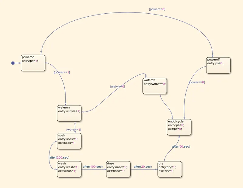
d)The chart that encloses all the necessary operations, is depicted below along with the model.
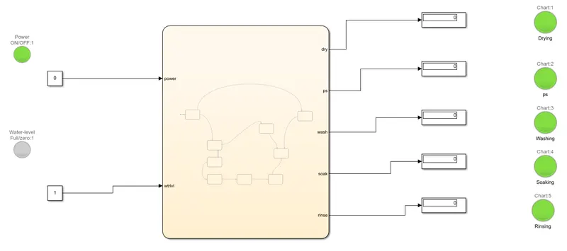
e)By slider switch input is set as 1 for on for both water and 0 off.
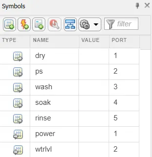
f)The input and output for the stateflow is defined in symbol pane after making the blocks and defining transition statements as defind below:
g)Each state after check of water input happens for a certain time.
h)The output for all states namely soak,wash,rinse and dry are set as 1 at entry and exit and for the termination state output is set as 0 at entry at exit.
i0)Transition statement between each states represents the time for which each action happens. All this are given in format of after(time,sec). The time values are soak: 200 sec, wash:100 sec, rinse:20 sec, dry:50 sec post which the state end of cycle is given.
k)LED is used to represent each state of cycle . Total run time=370 sec.
Q2) Make a Simulink chart for the “Gear shift” logic as per below conditions:
Speed Range(kmph) Gear
0 to 15 1
16 to 25 2
26 to 40 3
41 to 60 4
Above 61 5
Give speed input while the simulation is running & display the gear number.
Ans. A gear shift mechanism for a manual transmission includes a shaft axially movable for selecting shift planes and rotatable for engaging the gears defining the shift planes. The shaft is held in a reference shift plane by two helical springs.
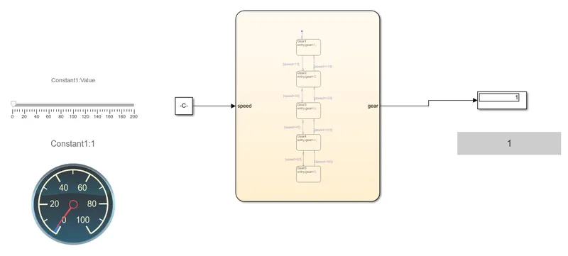
Simulink Model-
Blocks and parameters-
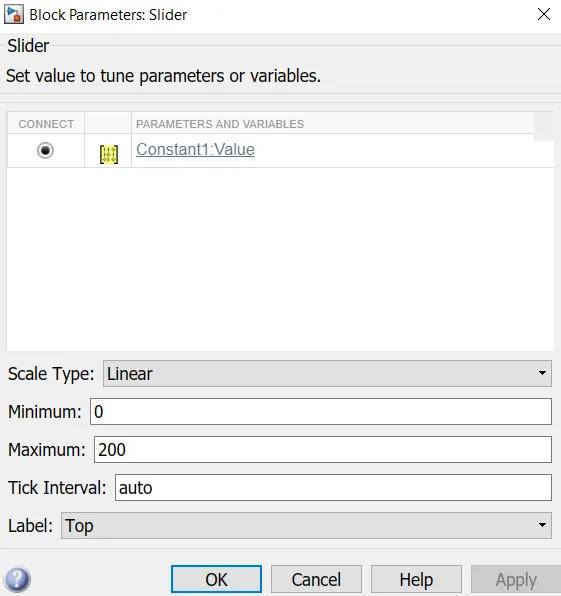
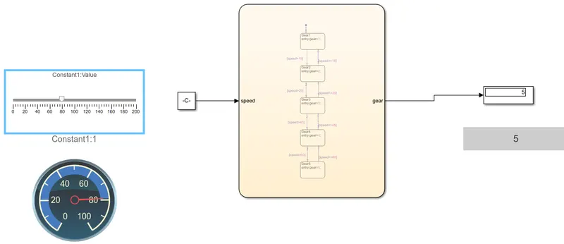
We start off by introducing the slider block setting max speed of the vehicle upto 200 km/hr and also a custom guage and connect these to the constant block.
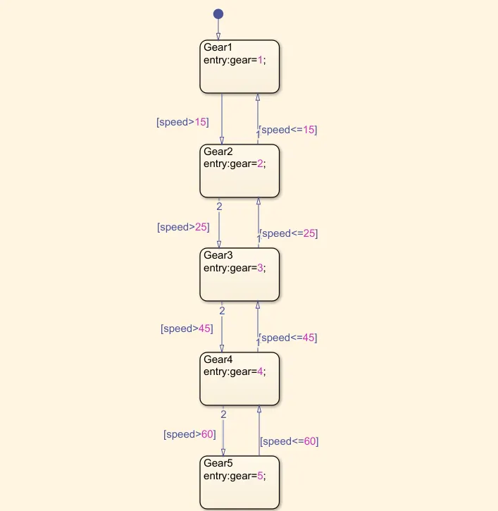
Gear shift logic:
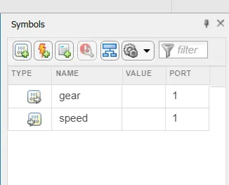
The input and output for the stateflow is defined as shown below:
Output- Speed inputs along with gear along with all the gear numbers are shown below,
Gear 1 when the speed is below 15 km/hr
Gear 2 when the speed is between 16-25 km/hr
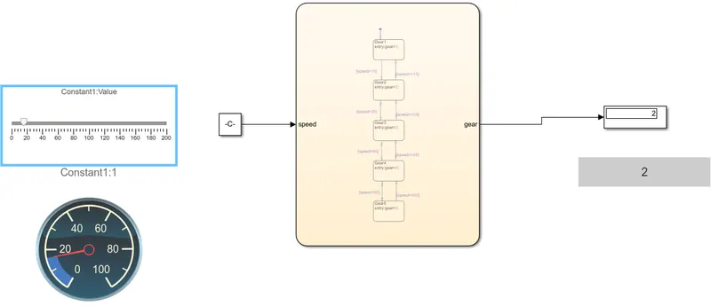
Gear 3 when speed is between 26-40 km/hr
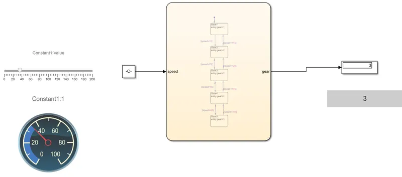
Gear 4 when speed is between 41-60 km/hr
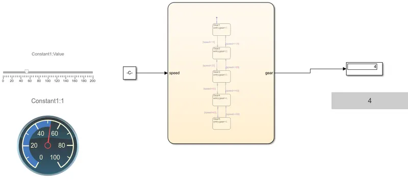
Gear 5 when speed is above 60 km/hr