Week - 4
-
- Implement control logic of a “washing machine” using Stateflow as per given sequence:
- If the power supply is available, the system gets activated
- If the Water supply is not available, stop the process & indicate through LED
- Soaking time should be 200s followed by Washing time of 100s.
- Then rinsing happens for next 20s & dryer runs for 50s
A.
- In simulink library under simulink real time stateflow option will be available in which various blocks such as chart,sequence viewer,truth table and state transition table.
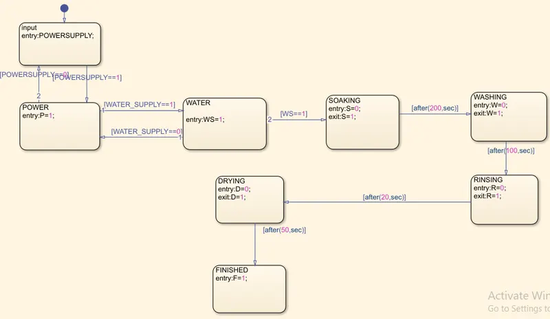
- select chart and in chart drag state block and transition arrow then in state block entry,during and exit parameters are given to execute while running and using state transition arrows conditions can be set and when the condition is met the transition is done from one state block to another.
- In the first state block power supply is named and when the condition is trueor on , the transition is done to second that is power and p=1 is displayed and also when water supply is on the condition is met and the transition is done.
- Then the soaking happens for 200 seconds and then the transition is done, washing happens for 100 seconds.
- Transition is done,rinsing happens for 20 seconds and transition is done,drying happens for 50 seconds and then process gets finished.
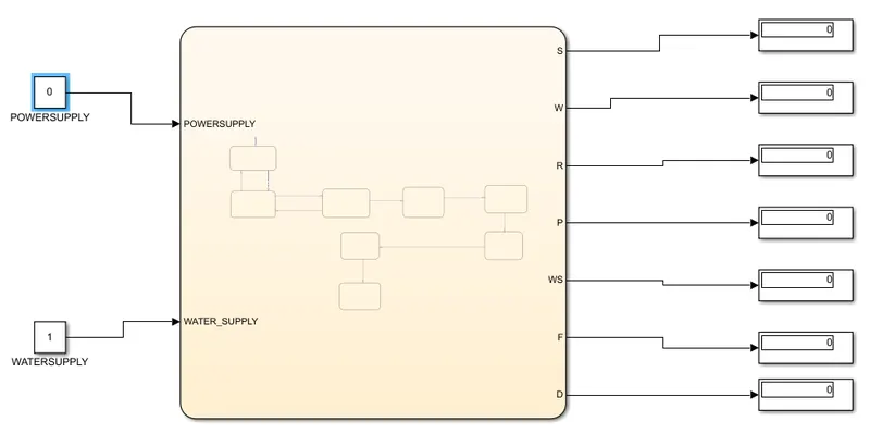
- when power supply is not given and water supply is given the output display shows power is off, all others.
- As i am using matlab r2018b blocks such as slider switch and lamps were not functioning and hence i didn't use them to showcase the simulation work properly.
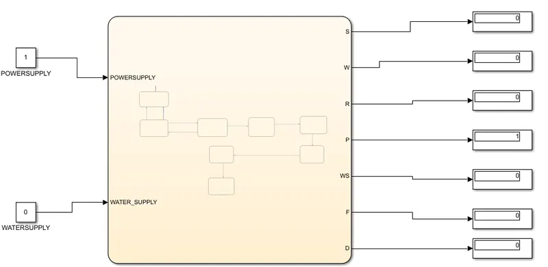
- when power supply is given and water supply is not given the output display shows power is on, all others are off.
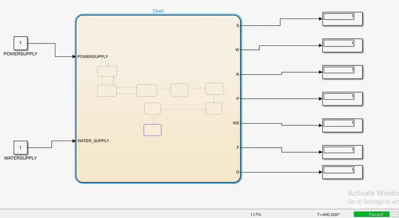
- when both are on,all the processes run and display that they are completed.
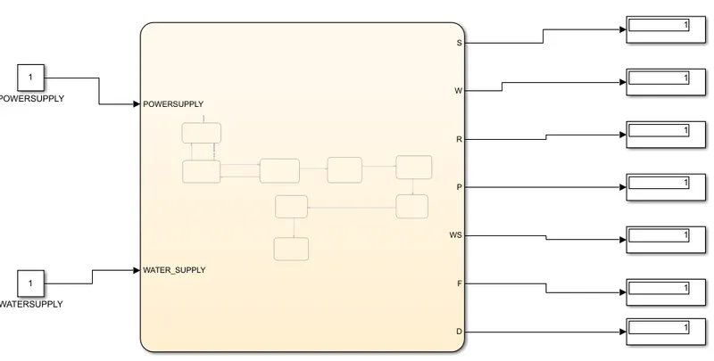
- The process happening is explained in detail in following steps
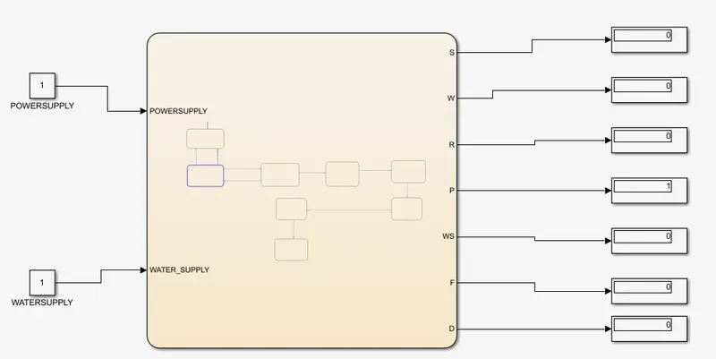
- For the first 5 seconds power on is displayed and later by 20 seconds water supply on is dispalyed .
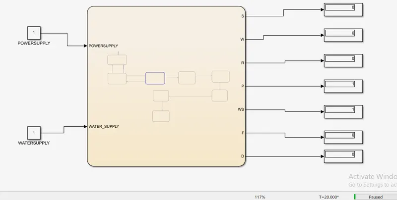
- Soaking happens by 230 seconds,and completion signal is displayed.
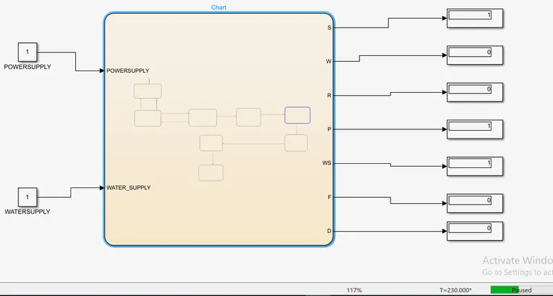
- Followed by washing of 100seconds i.e by 330 seconds completed and signal is displayed.
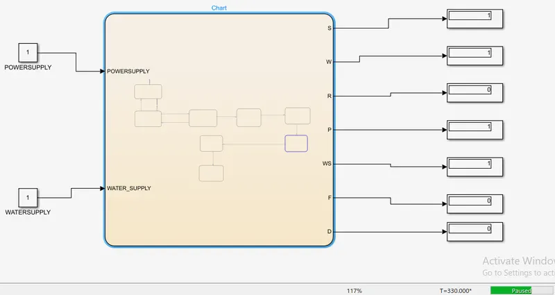
- Rinsing happens for next 20 seconds and by 360 seconds signal is displayed as shown in the figure.
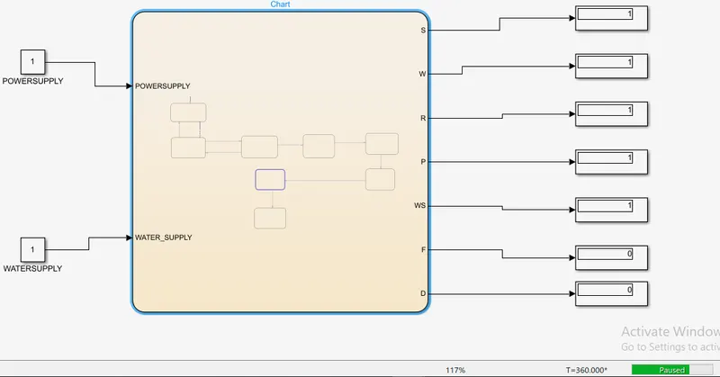
- And finally drying happens for 50 seconds , completion signal is displayed along with the finished signal by 400 seconds.
-
Make a Simulink chart for the “Gear shift” logic as per below conditions:
Speed Range(kmph) Gear
0 to 15 1
16 to 25 2
26 to 40 3
41 to 60 4
Above 61 5
Give speed input while the simulation is running & display the gear number.
A. - From simulink library,chart available in stateflow is selected and a state block is selected for giving input speed.
- For transition the condition for first gear the speed should be between zero and 15km/hr then for second gear the speed should be greater than 15km/hr to 25 km/hr the conditions are applied on state transitin arrow.
- Similarly for the third gear,fourth gear the speed should be between 26 km/hr to 40 km/hr and 41 km/hr tp 60 km/hr
- Finally for fifth gear the speed should be above 61 km/hr.
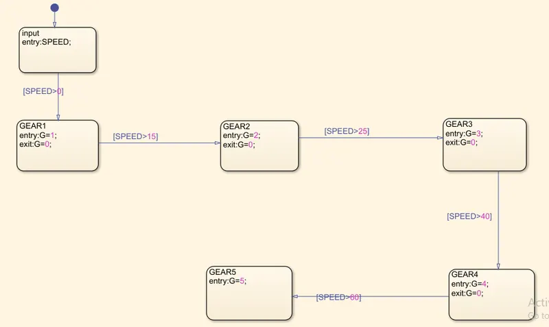
- The simulation is done and the results are displayed for determination of every gear.
- When input speed is 0 kmph the output is zero.
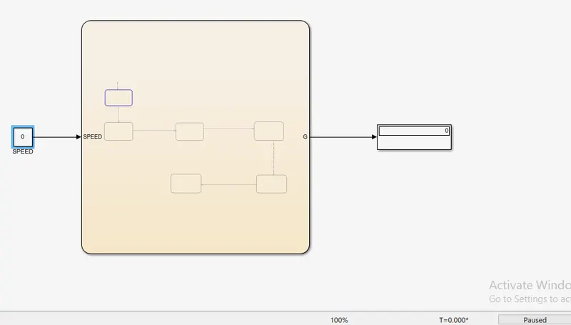
- When input speed is 10 kmph the output gear is one as shown in the figure below.
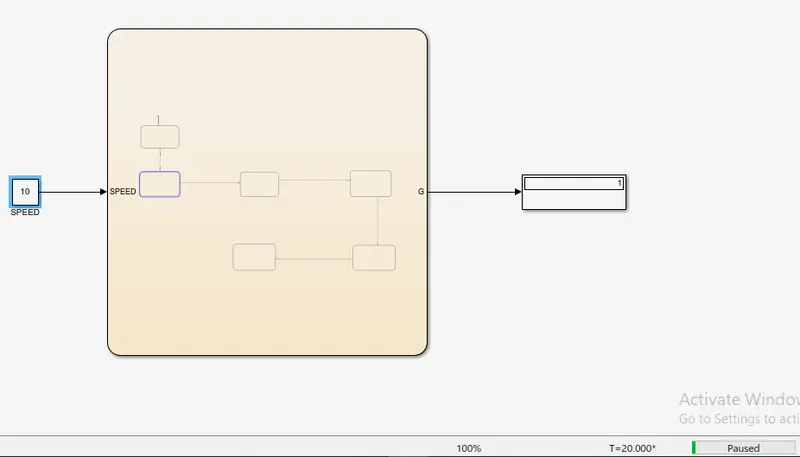
- For speeds above 15 kmph ,below 25kmph i.e when input speed is 20 kmph the output gear is two.
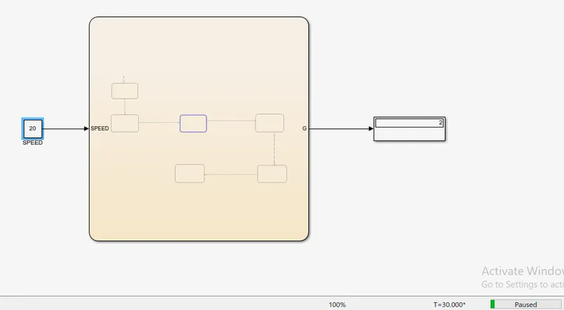
- For speeds above 26kmph, below 41kmph i.e when input speed is 30 kmph the output gear is three.
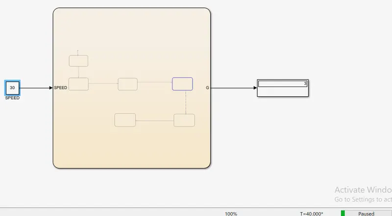
- For speeds above 41 kmph ,below 61kmph i.e when input speed is 50 kmph the output gear is four.
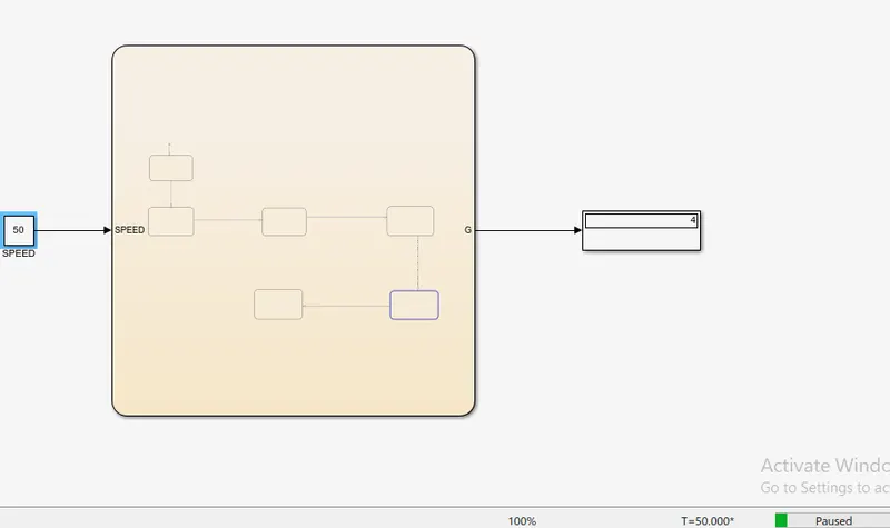
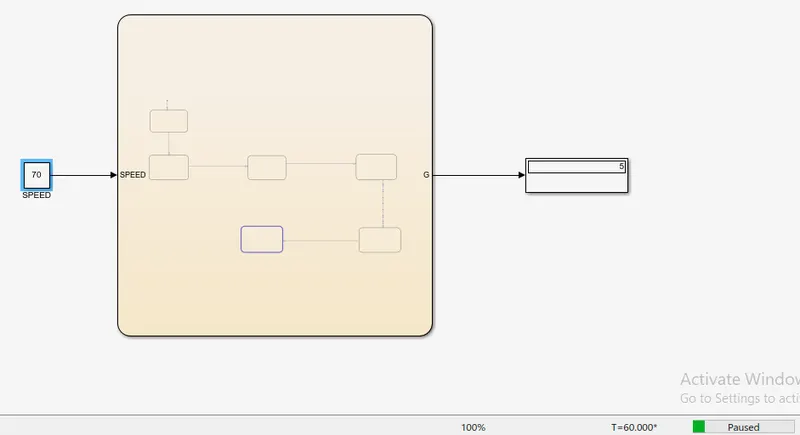
- For speeds above 61kmph i.e When input speed is 70 kmph the output gear is five.