Week - 4
Question 1:
Aim: To implement control logic of a “washing machine” using Stateflow as per the given sequence.
Objective:
- If the power supply is available, the system gets activated
- If the Water supply is not available, stop the process & indicate through LED
- Soaking time should be 200s followed by Washing time of 100s.
- Then rinsing happens for the next 20s & dryer runs for 50s
After all the processes have been completed turn on the finished LED.
Introduction:
Stateflow - Stateflow is a control logic tool used to model reactive systems via state machines and flow charts within a Simulink model.
Difference between Simulink and Stateflow-
Simulink is used to respond to continuous changes in dynamic changes. Stateflow is used to respond to instantaneous changes in dynamic changes.
A washing machine is a machine used to wash various types of clothes without applying any physical effort. The washing machine enables you to wash your clothes automatically without having to supervise its operation. All you have to do is put the clothes in the machine and select the wash mode. The washing machine automatically takes in the amount of water and detergent required and it also automatically sets the timer for washing, rinsing, and drying as per the selected mode and the number of clothes.
Stages of washing machine:
1. Soaking
2. Washing
3. Rinsing
4. Dryer
Simulink Model:
Conclusion:
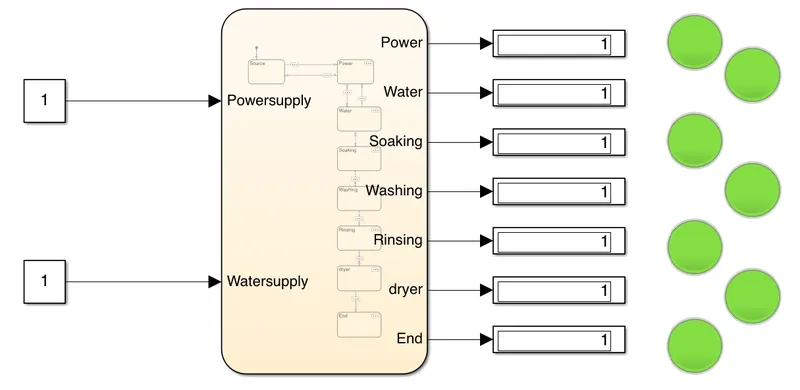
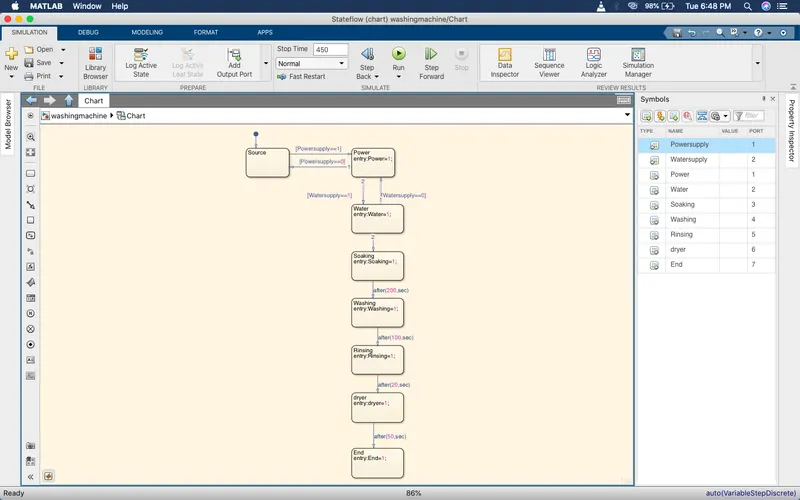
From the Simulink model, it is seen that the for logic system i.e chart we have given two inputs of power supply and water supply where the output is observed at every stage of power, water, soaking, washing, rinsing, dryer, and stop at the end.
From the State machine, logic is given according to the data given and inputs and outputs are stated in the symbol pane.
Question 2:
Aim: To make a Simulink chart for the “Gear shift” logic as per the below conditions:
Objective :
Speed Range(kmph) Gear
0 to 15 1
16 to 25 2
26 to 40 3
41 to 60 4
Above 61 5
Give speed input while the simulation is running & display the gear number.
Gear Mechanism:
It is clear that shifting between the gears is required for the smooth driving of the vehicle. The mechanism used for gear shifting is called a synchronizer. Basic purpose of the synchronizer is to engage the teeth of the sleeve and gear which are rotating at different speeds during the shifting of the gear.
Conclusion:
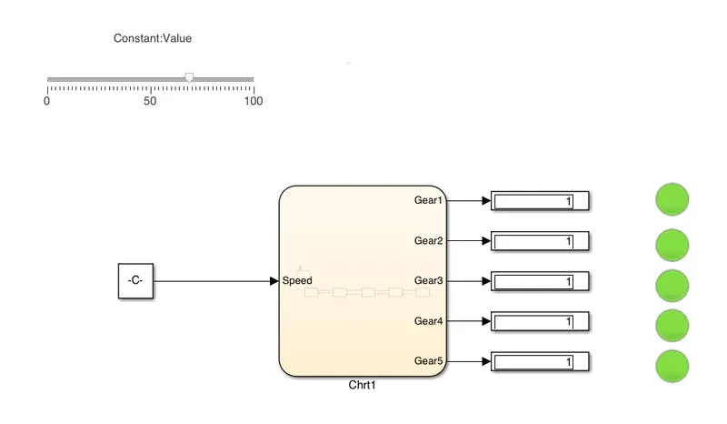
From the Simulink mode, it is seen that speed is given as input to gear logic which is connected with a slider to change the speed from 0-100, then the output of different gears is connected, according to the speed change output is observed.
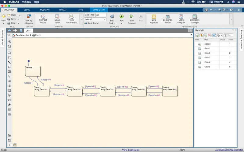
In Gear logic, conditions are given as per the data given and inputs and outputs are stated as given above in symbol pane.