Week 4 - 2D Meshing for Sheet Metal
Aim:- For the given CCB CAD model, Check for the Geometry cleanup (if required), Take the mid surface, and Mesh it.
Objective:- To take check the geometrical quality of the given model. Taking the midsurface of the given model after checking for the feometrical errors. Extracting midsurface of the given model with proper thickness. Check the geomtrical errors in the midsurface and correcting if any. Generating a mesh with proper flow. Checking if there is any errors and correcting that errors to generate proper and mesh with less tria percentage.
Quality Criteria:-
|
S.No |
Quality Criteria |
Value |
|
1 |
Target/Average length |
5 |
|
2 |
Minimum Length |
3 |
|
3 |
Maximum Length |
7 |
|
4 |
Aspect |
3 |
|
5 |
Warpage |
15 |
|
6 |
Skewness |
45 |
|
7 |
Jacobian |
0.7 |
|
8 |
Minimum Quad Angle |
45 |
|
9 |
Maximum Quad Angle |
135 |
|
10 |
Minimum Tria Angle |
30 |
|
11 |
Maximum Tria Angle |
120 |
|
10 |
Tria Percentage |
15 |
Given CAD Model:-
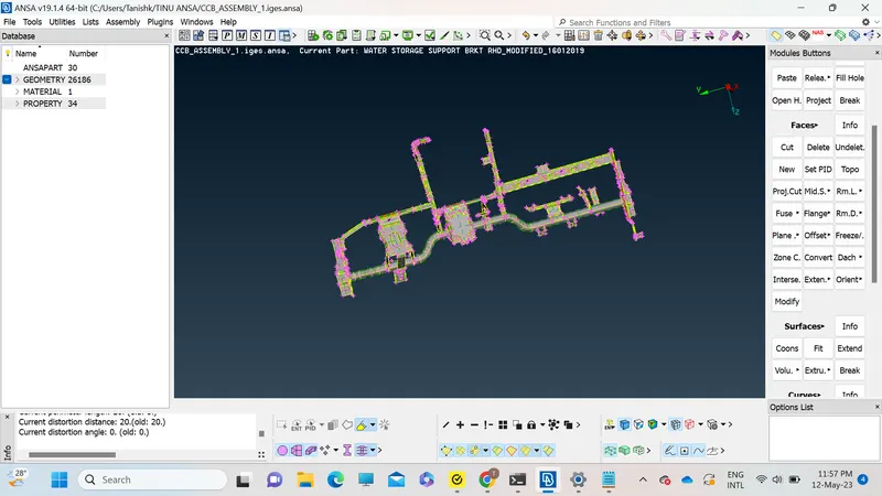
Procedure:-
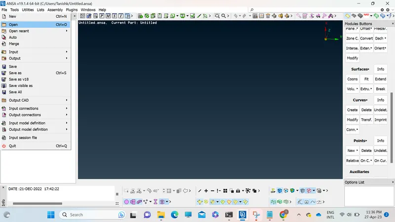
1. Open the giving model in Ansa software using open tab in file menu.
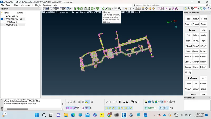
2. Do the check geometry on the given model using checks tab for checking if there is any geometrical issues in the model.
3. After checking the geometry fix the issues if any otherwise move on to the next step.
4. After checking the geometry of the model the next step is to extract the midsurface from the model. For extracting the midsurface there are two methods that we can use first is offset in the faces button and the other is Midsurface from faces buttons.
In the offset method we have to manually give the thickness at which we need to extract the midsurface. In the given model the thickness of the model is 1.6 so we have to take midsurface at 0.8 with proper direction.
The other method is automatic midsurface in that the saftware autodetects the thickness of the model and create midsuface acording to the model and its thickness. In automatic midsurfacing we do not have to provide thickness of the model.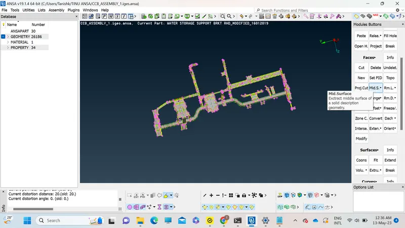
After creating the midsuface we once again go for the Quality check to see if the midsurface is turned out correct or not. If the midsurface in showing some errors we resolve those errors otherwise we move on to the meshing part.
Meshing :
For meshing we select the midsurface of the model. After selecting the midsurface we have to give the perimeter length to the midsurface and check if each and every component is greater that that given length/ perimeter. If some of them is less than that perimeter/ length we have to correct it in a manner that model is not destructured or deformed. After checking every component and resolving every error we can move on with the Quality Criteria. Quality Criteria for meshing is as follows:
|
S.No |
Quality Criteria |
Value |
|
1 |
Target/Average length |
5 |
|
2 |
Minimum Length |
3 |
|
3 |
Maximum Length |
7 |
|
4 |
Aspect |
3 |
|
5 |
Warpage |
15 |
|
6 |
Skewness |
45 |
|
7 |
Jacobian |
0.7 |
|
8 |
Minimum Quad Angle |
45 |
|
9 |
Maximum Quad Angle |
135 |
|
10 |
Minimum Tria Angle |
30 |
|
11 |
Maximum Tria Angle |
120 |
|
10 |
Tria Percentage |
15 |
We have to put the above quality criteria and apply them to the given model.
Press fn+ f11 to open the Quality parameter tab
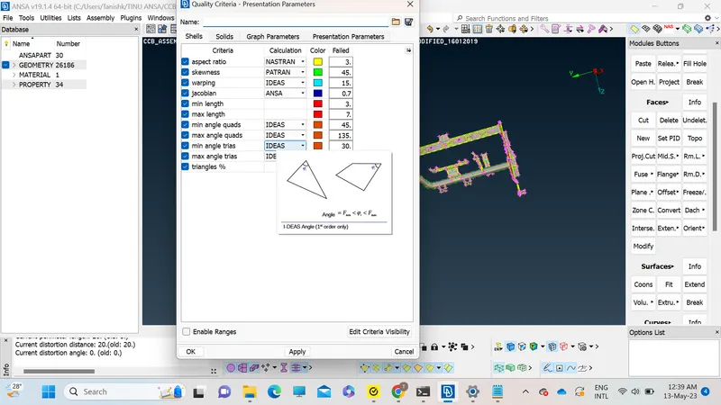
Now open the presentation parameters tab in quality criteria, turn on Elements% in graphics. Also set details on demand effect to all details and hit apply button.
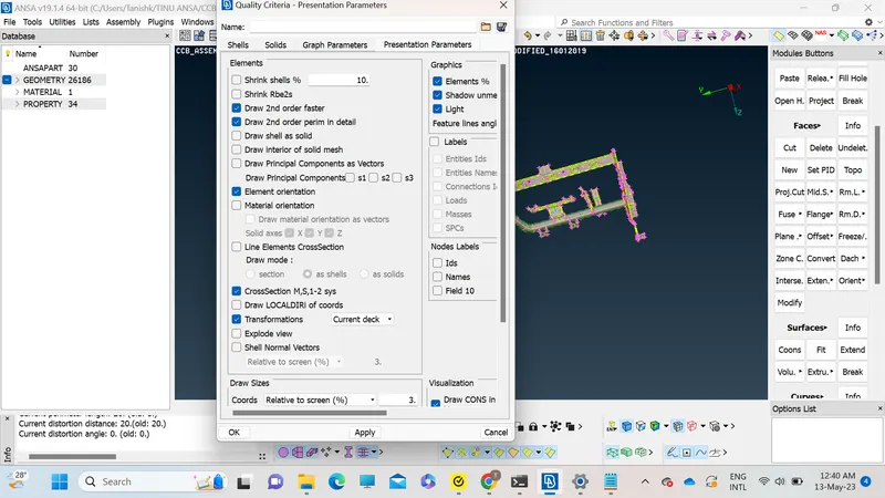
For the given model we do the midsurfacing part wise so we extract midsurface of one part do the meshing on that part and repeat the same procedure throughout the model.
For meshing we have to go to the mesh generater option in that select best. Firstly we have to mesh difficult parts cause they consume most of the time. Make sure to turn on the hidden mode cause that where we can see where the issues are at. Try to get as less trias as possible cause that affects the flow of the mesh. Do the mesh for whole model following the same method.
Conclusion:
We have successfully completed midsurfacing and meshing of the given model.