Week 4 - 2D Meshing for Sheet Metal
AIM OF THE CHALLENGE :
The followings are to be done in this challenge i.e, Week 4 - 2D Meshing for Sheet Metal
1- Geometry clean up
- Cons Resolution
- PID Generation if required
- Geometry check and rectify if any geometrical erroe found
- Check the orientation
2- Mid Surface generation
3- Mesh generation and improve mesh flow by maintaining quality criterial and low tria concentration
4- Thickness Assignment to the 2D Meshed surface
Link of the Challenge-
https://drive.google.com/file/d/1CwjbDBQu8J-3_RYzVnDcGi0QQItYO0XP/view?usp=share_link
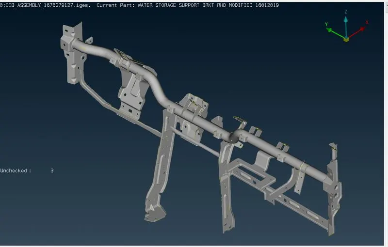
CAD MODEL OF THE CHALLENGE :
PROCEDURE :
The following procedure is followed by me to complete the challenge.
1- Geometry Clean up
- After importing the CAD Model 1st I have checked the PID to know how many diferent surfaces are in the model and got to know there are 34 PIDs . Then I have choosen one by one each PID to generate it's Mid surface and Meshing.
> Go to Lists Menu > Properties (CTRL+P) > Just Highlight the bulb symbol of the property ID which you want to show
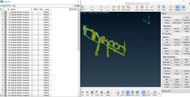
- For example I have choosen PID 2 to work on it and the I have done the Cons Resolution to know the exact shape of that PID.
> Go to Mesh Module > Choose Clasic Mesh > Click on length option of Perimeters group of the dropdown list > select the whole PID (For cons resolution the length should be 1 mm) and give the required length.
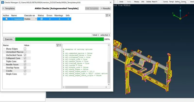
- Then I have done the geometry check to identify the geometrical error and rectified it by autofix option.
> Go to Tools Menu > Checks > Select the Geometry option > Click the Execute after selecting the parameters for which you want to check > Then fix the error by by right click and fix option from drop down menu
- Then I have done the orientation check and the orientation was correct.
2- Mid Surface Generation
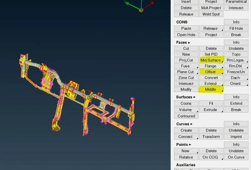
- After Geometry clean up I have generate mid surface of each PID by using Skin sub option of Midsurface option or Offset option or Middle (Both Single and Multi Sub option) according to the requirement and also generate PID for each mid surface to access that mid surface easily.
>Go to TOPO Module > Faces group > Mid Surface option > Select the Skin Sub option > Select the whole PID > Generate the Mid Surface by applying it
>Go to TOPO Module > Faces group > Offset option > Select the face which you want to offset > Then give the offset distance value > Generate the Mid Surface by applying it.
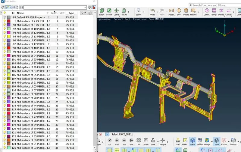
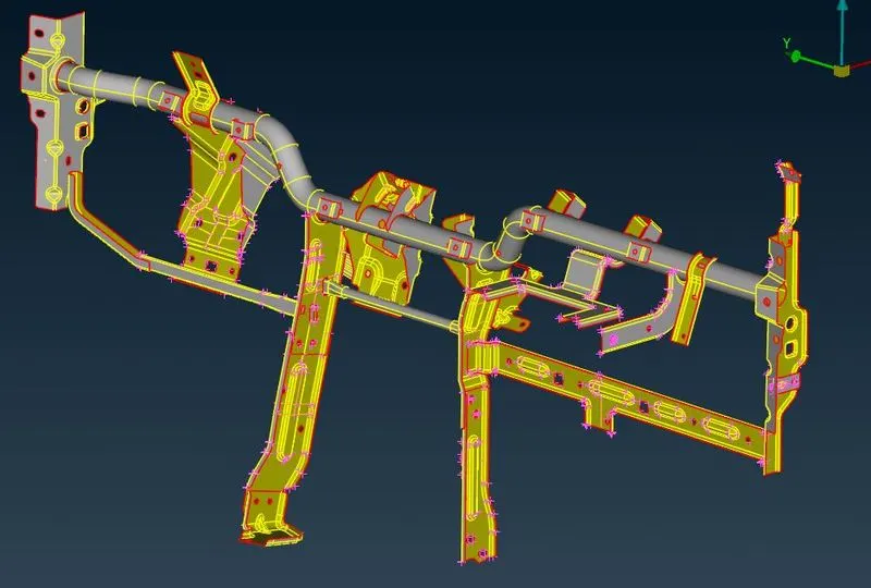
3- Mesh Generation and Maintaining the quality Criteria
by using the following procedure for all the midsurface one by one
- After Mid Surface Generation I have given the Element Length for both Perimeter and Macros area.
> Go to Classic Mesh from the drop down menu of Mesh Module > Go to Perimeters group > Select the Length option > Select the perimeter option from the box > Select the whole PID and give the target element length > then select the Macros and repeat the same process as Perimeter element length.
- Then I have given the Mesh Parameters and Quality Criteria as given in the question.
> Go to Utilities Menu > Click on Mesh Parameters > Give Target Length
> Go to Utilities Menu > Click on Quality Criteria (f11) > Give required quality and its range
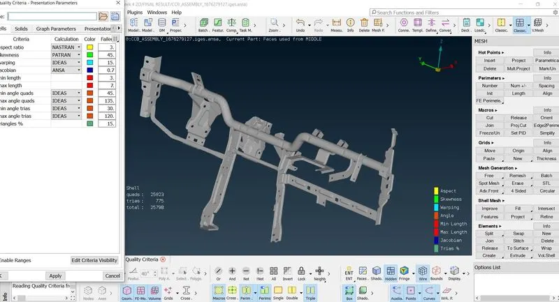
- Then I have generated the meshing of the surface by Best Mesh option.
> Go to Mesh Generation > Click on Best mesh > Select the surface you want to Mesh > Click the middle mouse button to execute
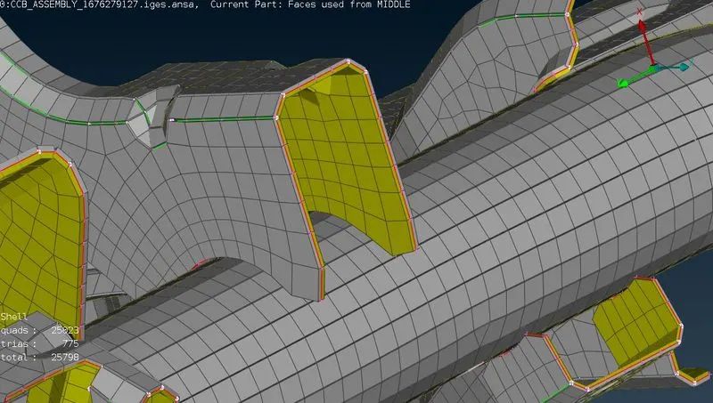
- The I have used different options like paste , split, reconstruct, smooth to improve mesh flow and to maintain Quality Criterial.
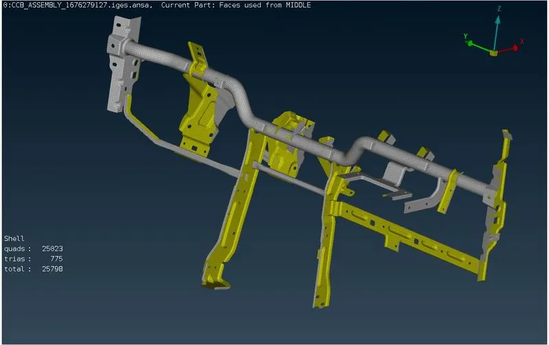
- Then I have assign Thickness to that component.
> Go to utillity menu > Quality Criteria option (Shortcut - f11) > Select Presentation Parameters from the drop down box > Select Draw Shell as Solid and apply it
LEARNING OUTCOMES :
- By doing this challange I have lerned the following points
- Got to know about the procedure to work on a FE Model
- How to Generate new PID
- How to Improve Mesh flow and Maintain Quality Criteri (Bette understanding of the functions of Paste, Reconstruct, Split, Smoot options)
- How to Check if you have any unmeshed surface is there.
- How to assign thickness to the mid surface
CONCLUSION :
In the process of doing this challenge I have faced some problems and with the help of Mentors I have learnt how to fix those errors and alos got a better understanding of the functionality of different options. Thank you all for that.
Link of the Challenge-
https://drive.google.com/file/d/1CwjbDBQu8J-3_RYzVnDcGi0QQItYO0XP/view?usp=share_link