Week 3 - 2D meshing for sheet metal
AIM OF THE CHALLENGE :
The followings are to be done in this challenge i.e, 2D Sheet metal meshing
1- Geometry clean up
- Cons Resolution
- PID Generation if required
- Geometry check and rectify if any geometrical erroe found
- Check the orientation
2- Mid Surface generation
3- Mesh generation and improve mesh flow by maintaining quality criterial
4- Thickness Assignment to the 2D Meshed surface
PROCEDURE :
The following procedure is followed by me to complete the challenge.
1- Geometry Clean up
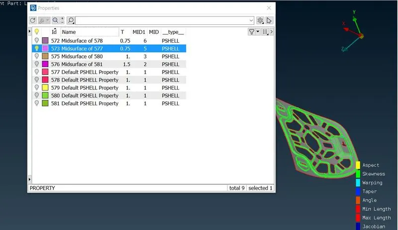
- After importing the CAD of Hood 1st I have checked the PID to know how many diferent surfaces are in the Hood model and got to know there are 5 PIDs and 2 of them are similar. Then I have choosen 1 PID to generate it's Mid surface and Meshing.
> Go to Lists Menu > Properties (CTRL+P) > Just Highlight the bulb symbol of the property ID which you want to show
- I have choosen the PID 577 to work on it and the I have done the Cons Resolution to know the exact shape of that PID.
> Go to Mesh Module > Choose Clasic Mesh > Click on length option of Perimeters group of the dropdown list > select the whole PID (For cons resolution the length should be 1 mm) and give the required length.
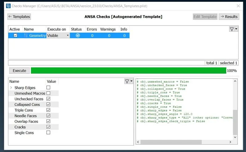
- Then I have done the geometry check to identify the geometrical errord and rectified it by autofix option.
> Go to Tools Menu > Checks > Select the Geometry option > Click the Execute after selecting the parameters for which you want to check > Then fix the error by by right click and fix option from drop down menu
- Then I have done the orientation check and the orientation was correct.
2- Mid Surface Generation
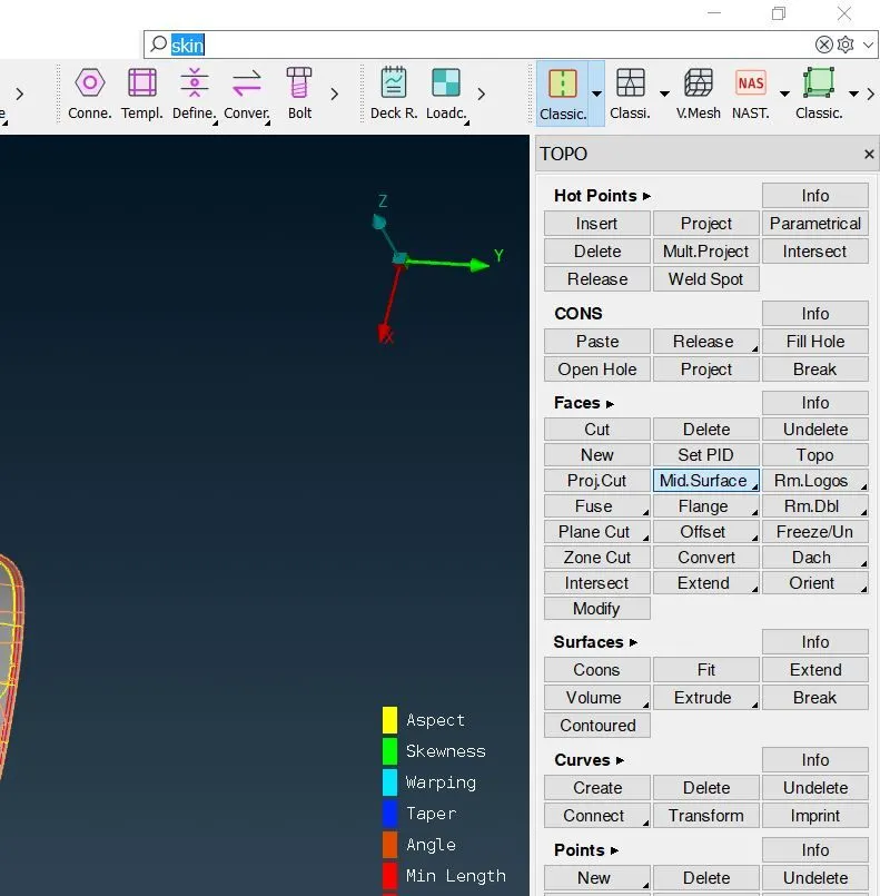
- This PID i.e 577 was a combination of multiple surface and was time taking and difficult to generate mid surface by "Offset" option. Therefore I have generated the Mid surface by using Skin sub option and gave a new PID to that mid surface.
>Go to TOPO Module > Faces group > Mid Surface option > Select the Skin Sub option > Select the whole PID > Generate the Mid Surface by applying it
3- Mesh Generation and Maintaining the quality Criteria
- After Mid Surface Generation I have given the Element Length for both Perimeter and Macros area.
> Go to Classic Mesh from the drop down menu of Mesh Module > Go to Perimeters group > Select the Length option > Select the perimeter option from the box > Select the whole PID and give the target element length > then select the Macros and repeat the same process as Perimeter element length.
- Then I have given the Mesh Parameters and Quality Criteria as given in the question.
> Go to Utilities Menu > Click on Mesh Parameters > Give Target Length
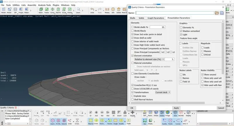
> Go to Utilities Menu > Click on Quality Criteria (f11) > Give required quality and its range
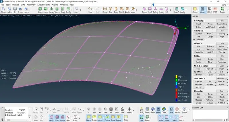
- Then I have generated the meshing of the surface by Best Mesh option.
> Go to Mesh Generation > Click on Best mesh > Select the surface you want to Mesh > Click the middle mouse button to execute
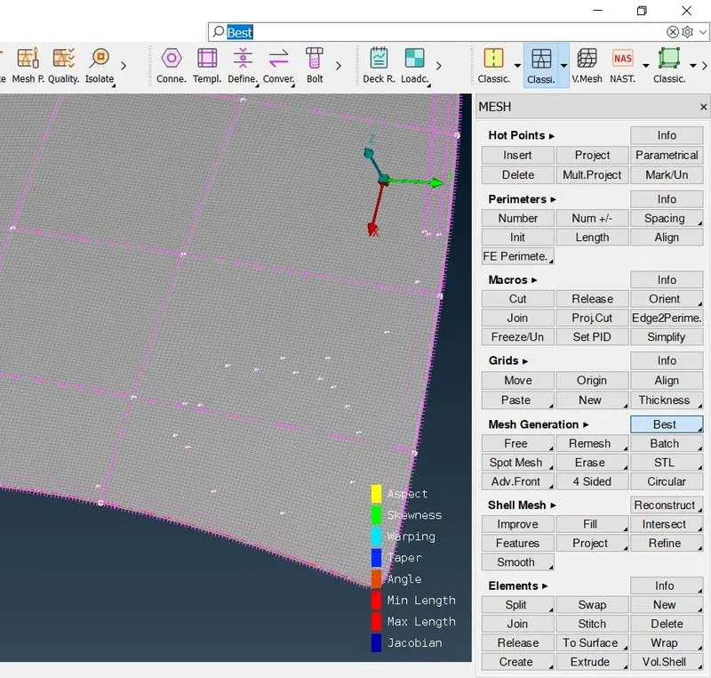
- The I have used different options like paste , split, reconstruct, mooth to improve mesh flow and to maintain Quality Criterial.
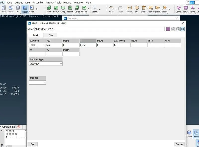
- Then I have assign Thickness to that component.
LEARNING OUTCOMES :
- By doing this challange I have lerned the following points
- Got to know about the procedure to work on a FE Model
- How to Generate new PID
- How to Improve Mesh flow and Maintain Quality Criteri (Bette understanding of the functions of Paste, Reconstruct, Split, Smoot options)
- How to Check if you have any unmeshed surface is there.
- How to assign thickness to the mid surface
CONCLUSION :
In the process of doing this challenge I have faced some problems and with the help of Mentors I have learnt how to fix those errors and alos got a better understanding of the functionality of different options. Thank you all for that.
A Special thanks to Hari Ram Sir for Mentoring me in live challenge session and helping me in completing the challenge.
I am unable to attach the ansa file because of over size (170 MB)