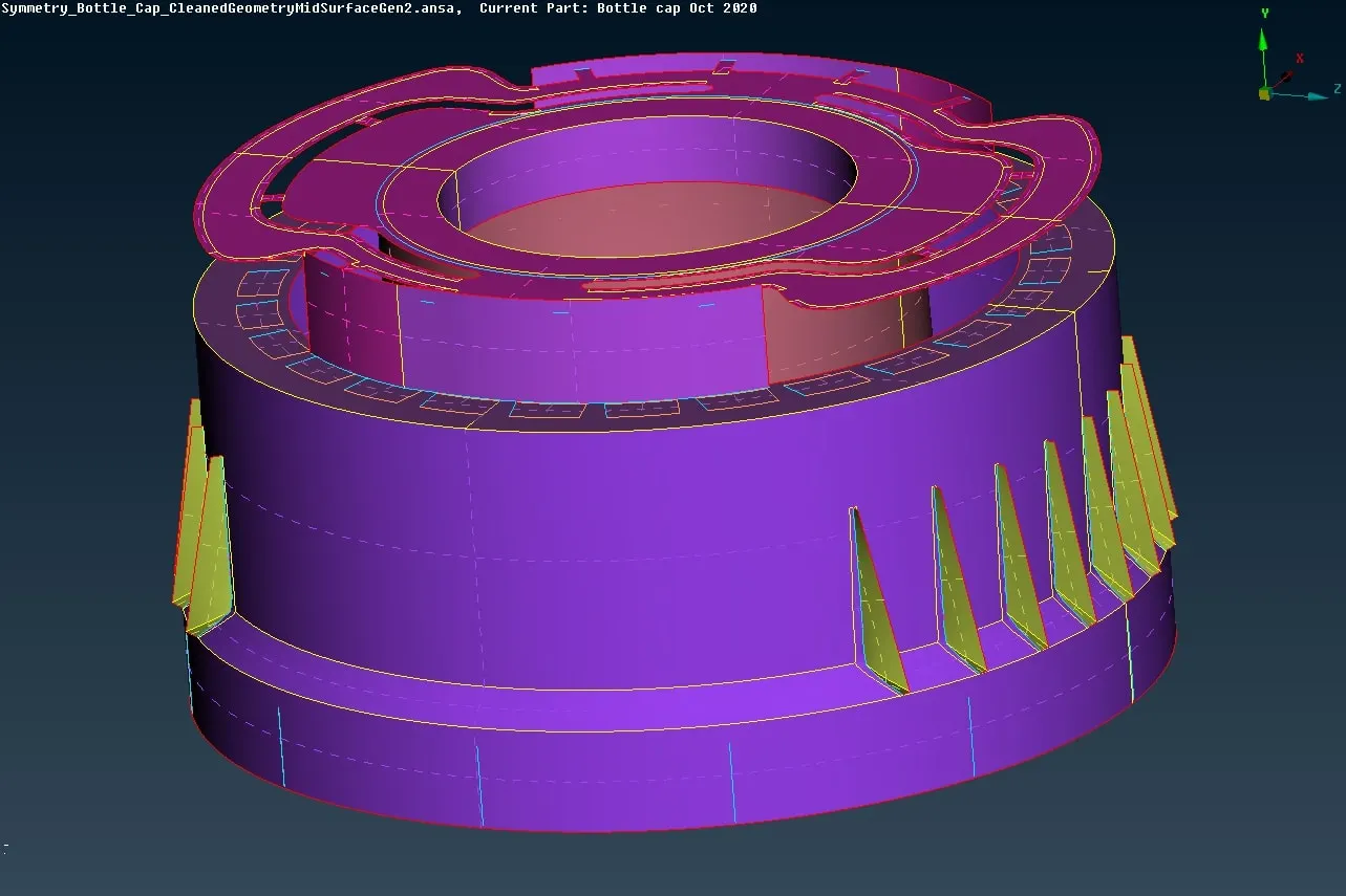
Week - 4 - 2D meshing for Plastic components
PRE-PROCESSING OF BOTTLE CAP USING ANSA
AIM : To mesh the given Symmetric Bottle Cap ( Plastic Component ) using pre-processing software ANSA.
OBJECTIVES :
- To check for geometry errors and clean it up using TOPO module for the given CAD Model.
- Generate a Mid - Surface of the geometry either manually or automatically.
- Apply the given quality criteria and define the mesh parameters and Generating the mesh.
- Mesh cleanup.
PROCEDURE :
- Importing the CAD Model
- Geometry Check and Topological activity
- Mid - surface generation
- Checking for open ends and completing the mid surface
- Mesh parameters and quality criteria setup.
- Mesh generation
- Set PID
IMPORT CAD MODEL -
The CAD Model in either IGS/STEP file given is imported into ANSA (Ctrl + O)
GEOMETRY CHECK -
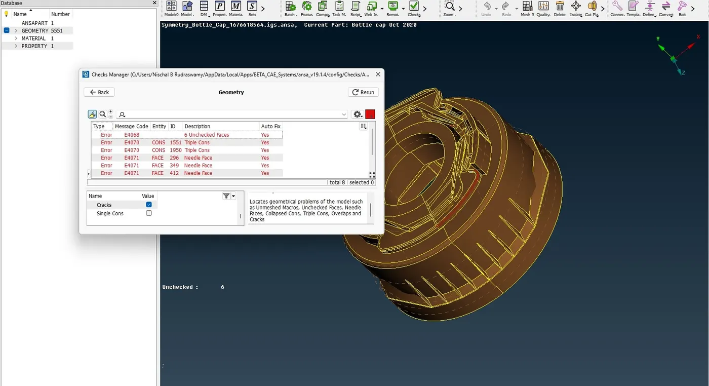
The imported CAD model is checked for geometrical errors using the Check Manager > geometry option. As the imported model may have some distortions and some defects, hence it is always recommended to check for the geometry before moving further down the established procedure.
TOPOLOGICAL ACTIVITY -
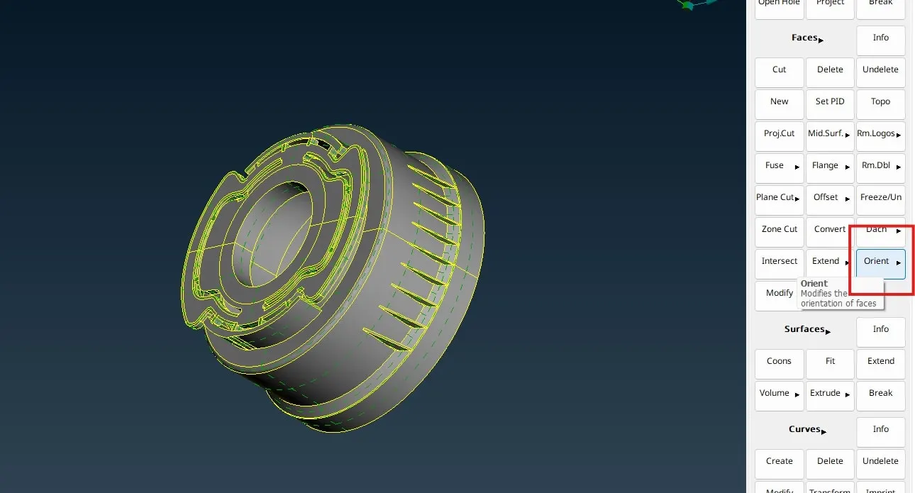
Fixing the single con errors needs manual intervention most of the times. One can also encounter Needle face, Unchecked faces and Triple Cons errors as well. TOPO Module/Deck is used for the Topological activity. The open faces with Single CONS are stitched using Faces > New. Triple CONS are released using Cons > Release. Additional single CONS are deleted using Faces > Delete. Other commands used during this phase are Hotpoints > Insert, Hotpoints > delete, Cons > Project and Curves module button used to create missing faces. After the Topological activity, the Geometry is checked once again. When the status is 100% clean, we use Faces > Orient to orient the faces.
MID - SURFACE GENERATION -
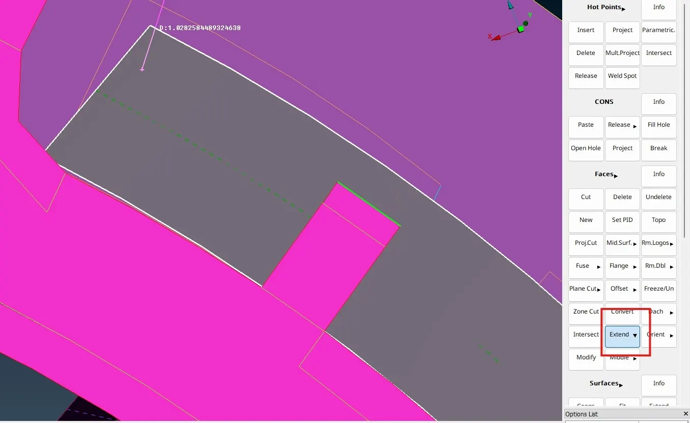
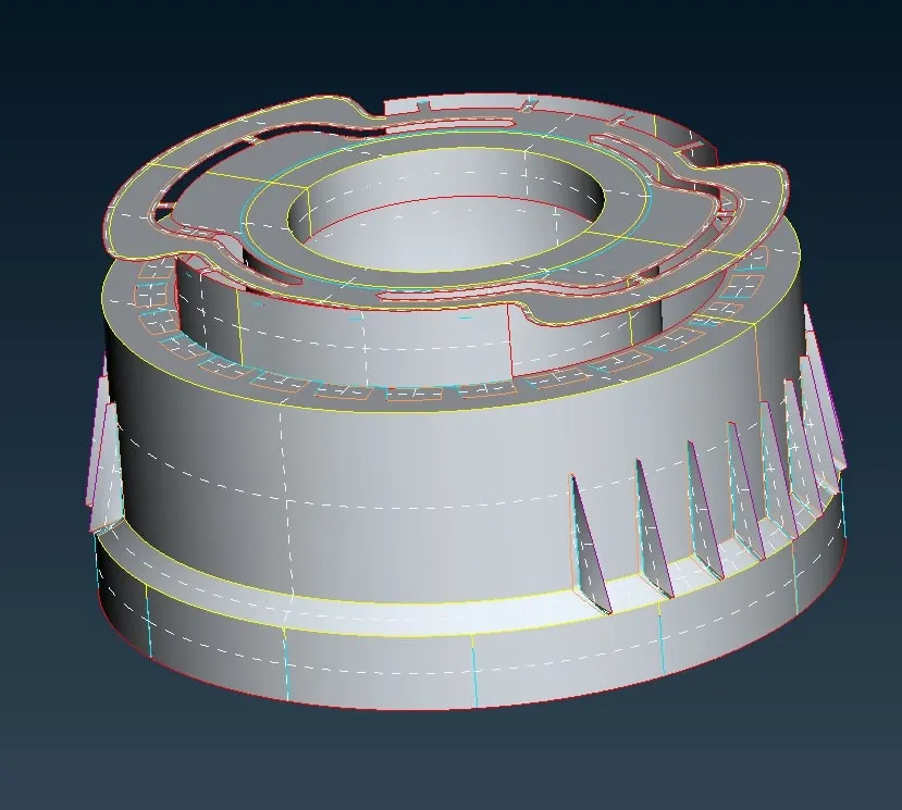
Mid - Surface can be generated by manual and Automatic methods . Automatic mid surface generation is usually done when the thickness of the model is uniform. Using Faces > Mid surface > Skin option we can generate a mid surface automatically with little inconsistencies. For the above given model I used Manual mid surface technique using Faces > Offset.
Before taking the mid surface one has to measure the thickness of the given CAD model on various sides and features so as to confirm the uniformity of the thickness which would help to decide whether to opt of automatic or manual mid surface generation method. Since the given geometry of Bottle cap had a complex and non - uniform thickness I adopted manual mid surface generation.
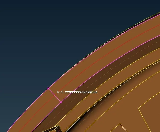
Using Faces > Offset , knowing the thickness, I generated the manual mid surface face by face.
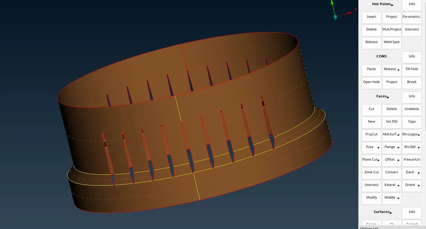
During the mid surface generation I encountered challenges regarding the tapered features and teeth features with varying thickness.
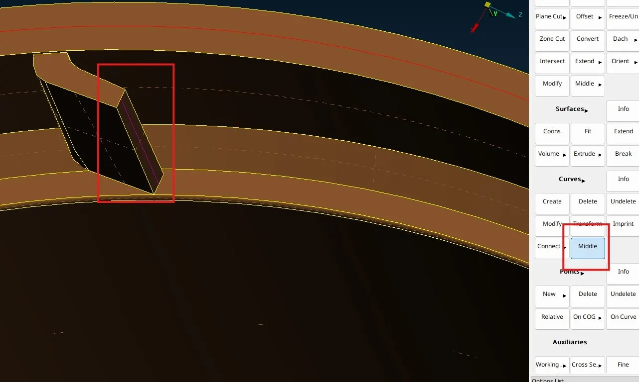
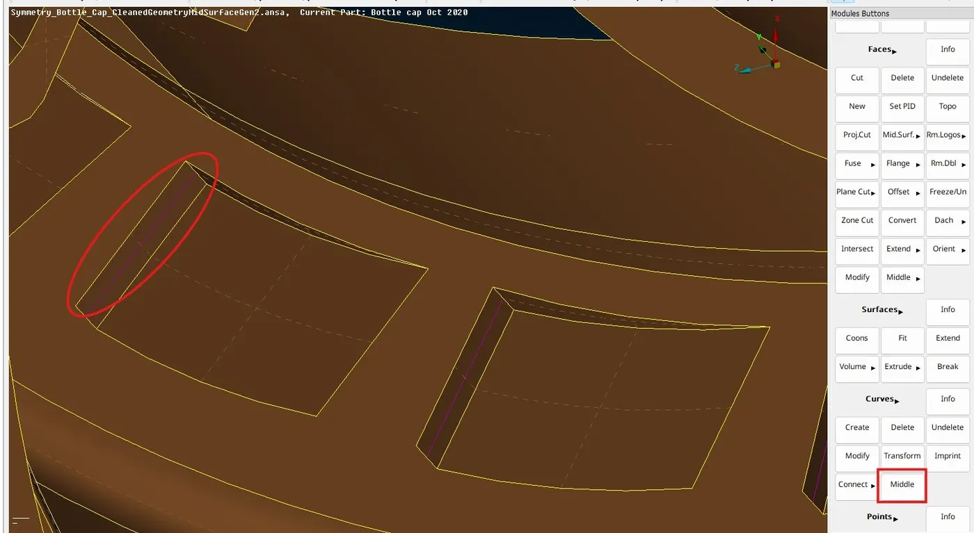
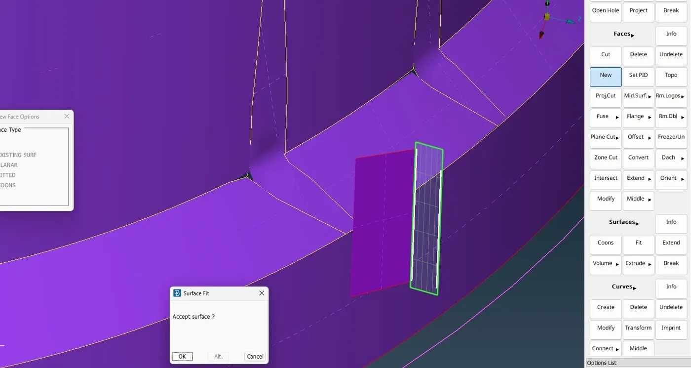
MESH PARAMETER AND QUALITY CRITERIA -
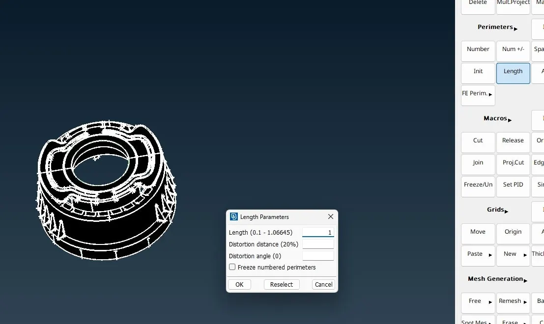
The Quality criteria (F11) is set up to given standards and then using MESH module, Mesh parameter is set using Parameter > Length for the given length. Also Mesh parameter can be set up in the Utilities > mesh parameter option as well.
MESH GENERATION –
This is under MESH module/Deck in ANSA. Again there are several options to generate mesh for a given model. Using Best or Spot mesh, it is for meshing macro elements one by one. Batch mesh generates the mesh for the whole body, taking into account the mesh parameters and quality criteria into account. Apart from that using TOPO > Face > Mid-surface > Casting, also generates auto mid surface and mesh. For the given plastic model I used Best mesh and spot mesh options in Mesh generation button.
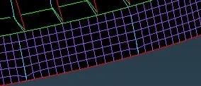
Mesh Flow Correction - This can be done using various module
buttons under MESH deck. Elements, Shell Mesh, Macros and Grid are some of
them. Using macros > cut, join; Elements > Split, join, swap one can
correct the mesh flow and keep the mesh adhering to the quality criteria
established.
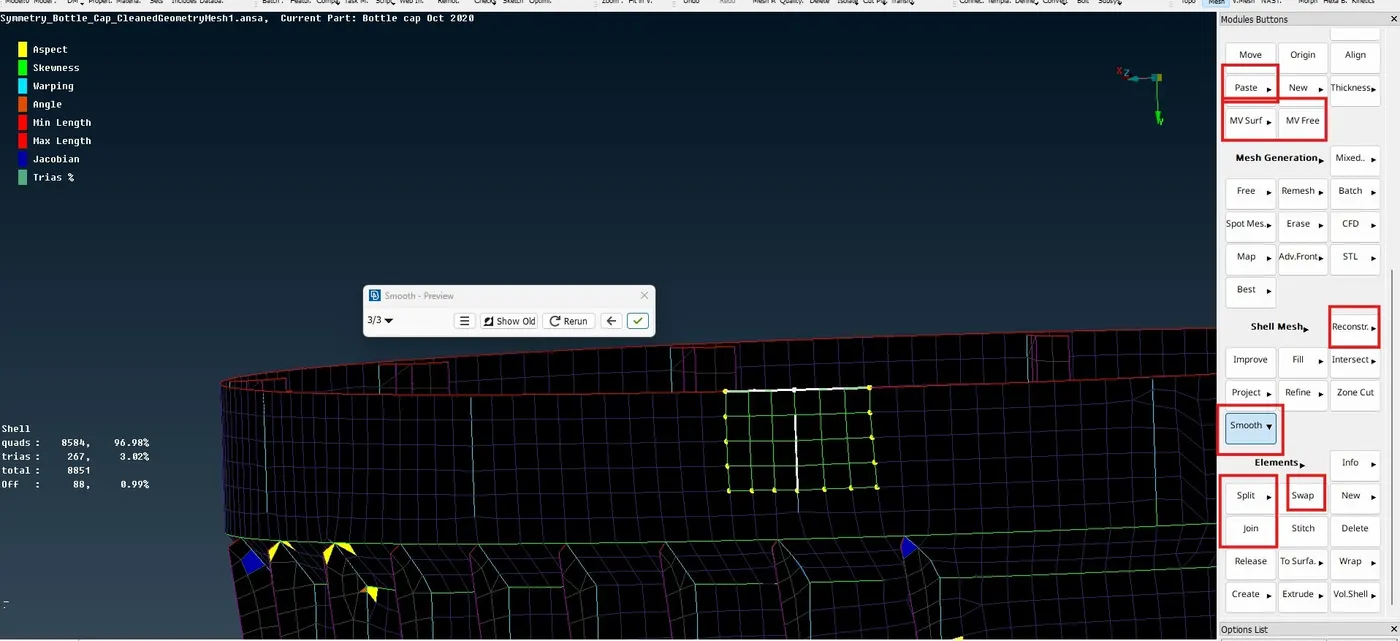
But Shell mesh > Reconstruct and Shell Mesh > Smooth operations are extensively opted to correct the initial mesh quality and flow discrepancies.
SET PID –
Final step in the procedure is to set PID using TOPO > Face > Set PID option, in order to account for varying thickness the PID is set and then the final mesh model is exported for the nest stage, that is for the solver.