Week - 4 - 2D meshing for Plastic components
OBJECTIVE
1. Import given model. File-open-select path-model.
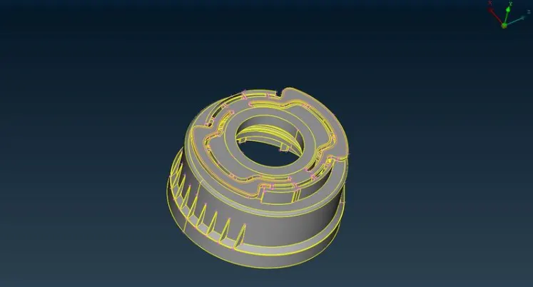
2. check for geometry cleanup. check the model for any type of errors like singlecon, needle, face, cracks etc.
check - geometry - execute
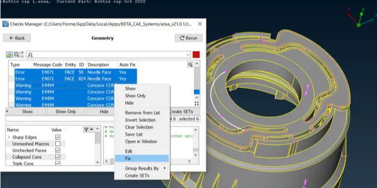
3. to cleanup errors. Select all the errors and select fix command for autofix the errors.
4. whichever error is not fixed through auto fix. fix the errors manually by selecting right tools from the topo menu.
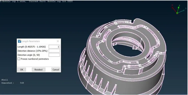
5. After geometry cleanup , next is to refine the macros and perimeter of the model for good resolution to see the components. give 1 as value by selecting
mesh-perimeter tool.
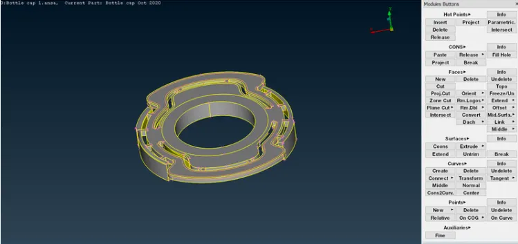
6. Now seperate the surface by using or, not, inot tools.
7. To get a idea to extract the midsurface for macros, measure the thickness of the model.
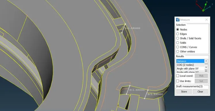
8. Thickness of the two surfaces are same overall we should use offset option topo - face - offset.
9. Assign value as half of the thickess and select the faces to offset. give negative value when the arrow in opposite side.click ok and click no to delete the surface for further references.
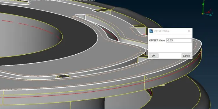
10. The model has varying thickness in some surfaces. those surfaces are extracted by using middle tool in topo module topo-faces-middle-single or multi .
11. For ribs we can use both but the surfaces are single. use middle-single. now select the first surface then click second surface. now click ok to accept surface. now the midsurface is generated.
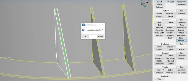
12. we have some threads in the bottle cap. it has trapezium shaped surface for those surfaces take midcurve to get a exact mid surface.
13. Topo-curve-middle select the two curves one by one and click ok to get mid curve.
14. now project the midcurve to midsurface topo-cons-project and now use those curves to create new surface using topo-faces-new. The midsurface is generated for threads.
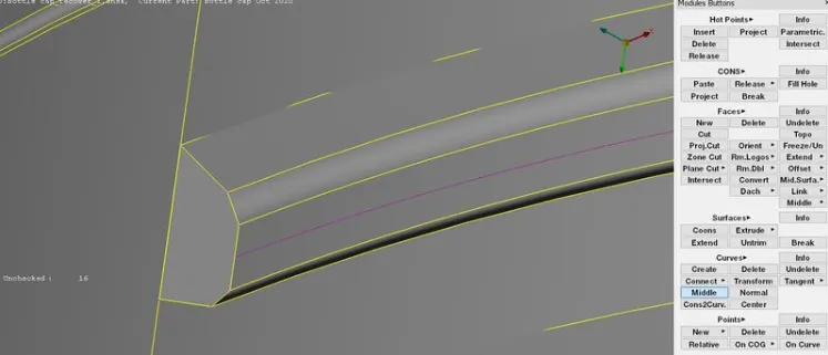
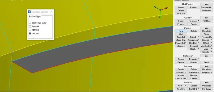
15. there are some ribs having varying thickness in the inner bottom of the model.
16. Use topo-faces-middle to get a midsurface for the rib and now extend the free edge topo-faces-extend select free edge and select the midsurface and the midsurface connected with the another major midsurface.
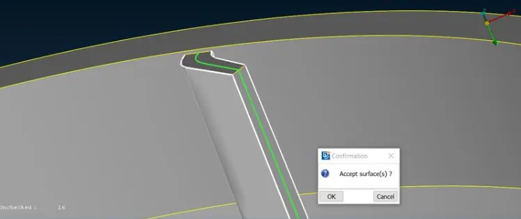
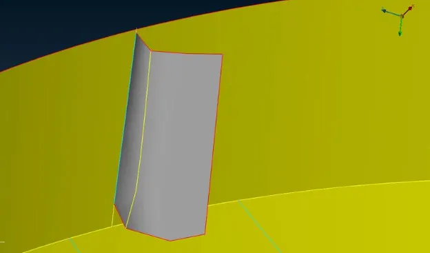
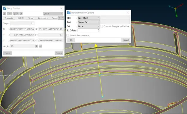
17. Now transform the ribs around the surface as copy by using Transform-copy-rotate select the midsurface of rib and select rotate.
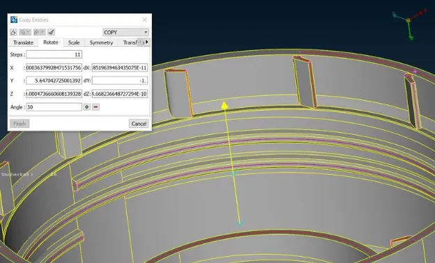
18. now give X & dx value for axis of rotation and give the copies and click finish to get a ribs.
19. For create axis of rotation we have to create COG points topo-points-on COG select the circle 1 and create COG point and select a cirle 2 above some height use those points for x & dx value.
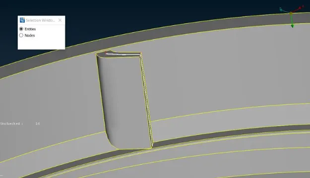
20. Now get a midsurface for teeths in the model.
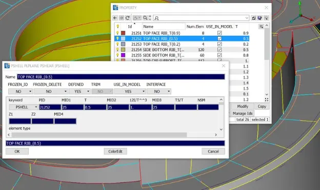
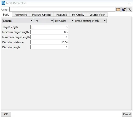
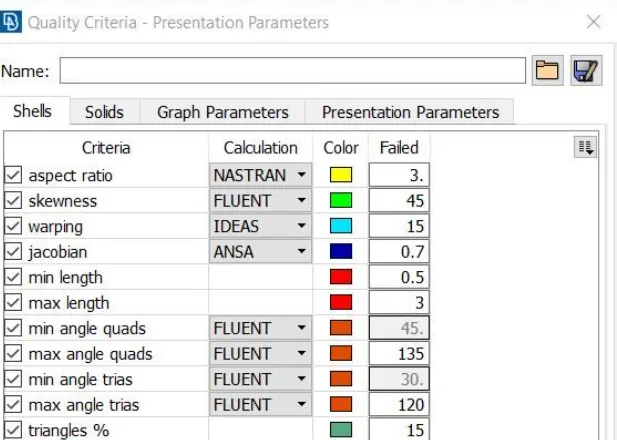
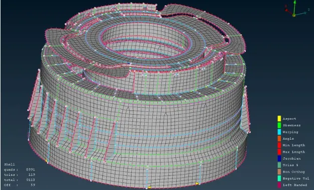
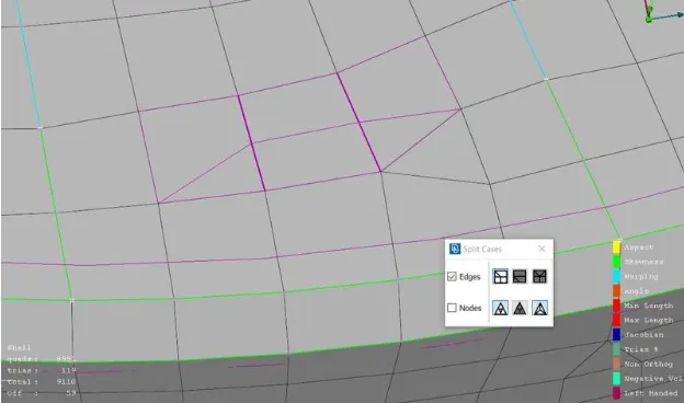
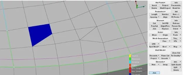
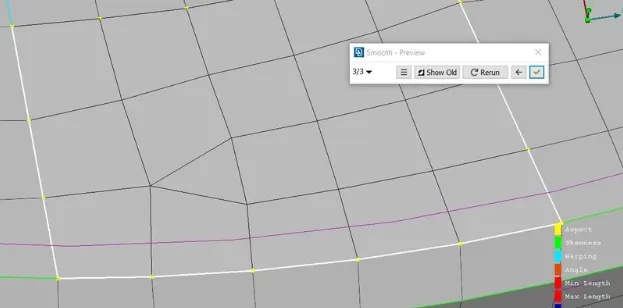
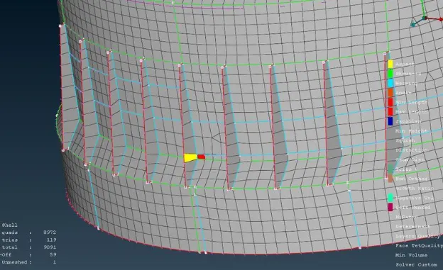
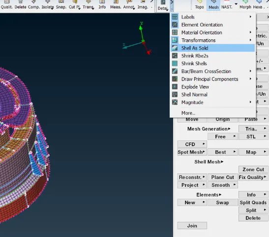
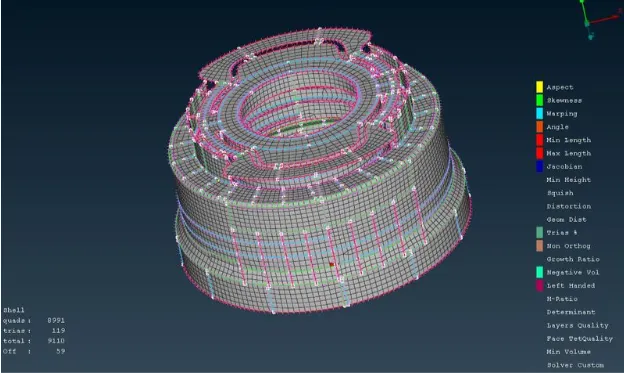
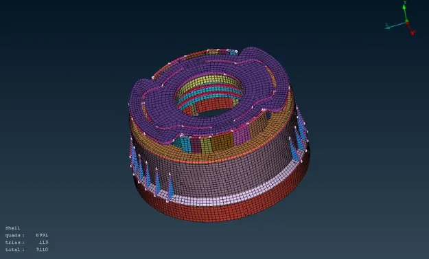
21. Use midcurve option to create a midcurve and project the opposite side con to the midsurface and click the midcurve and projected curve to create the new surface.
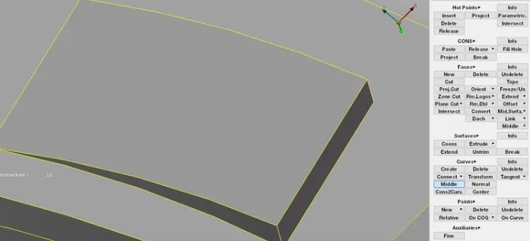
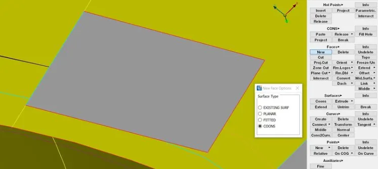
22. we will Follow the same procedure for transform the teeth.
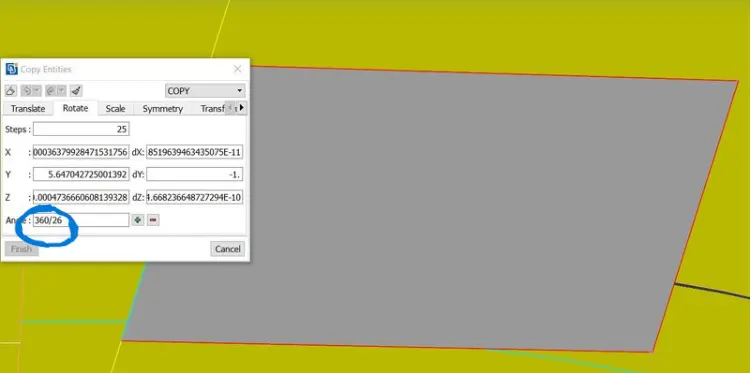
23. we have some more steps to create the copy. Select angle tab. Give value as 360/26 and click ok. The teeths are created around the surface.
24. Assign the thickness for the midsurfaces. There is some varying thickness surfaces so that will have to create gradual thickness variations under one surface.25. We can create property easily. select property-new-pshell-assign thickness-assign name.26. we can move to mesh the model. First set the mesh parameters. G27. Give target element length as 1mm, min length as 0.5mm, max length as 3mm. select ok.28. Now give quality criteria for the mesh. Select quality criteria and assign values as given in the above. Select presentation parameters. select elements percentage. Now click ok.29. First select the macros and select best mesh in the mesh generation (mesh-mesh generation-best).30. The mesh is generated in the selected macros. follow the same procedure for mesh generation.31. After that use reconstruct tool for remesh the exsiting mesh (mesh-shell mesh-reconstruct).31. Now Use split, paste, swap option for reduce the opposite trias, back to back trias in the exsiting mesh in the model (mesh-element-split/swap) (mesh-grids-paste).32. Now the mesh are generated. check for quality criteria and the failed elements are corrected using tool like smooth,reconstruct,fix quality, move in the mesh module. finally the mesh are generated for the given model.33. Some elements around the triple cons are failed for minimum length, aspect ratio. Those elements are under OFF elements.34. Select the draw shell as solid tool in presentation parameters tab to see the thickened solid pattern of the mesh.Final component images:Final Meshed Component: