Week - 4 - 2D meshing for Plastic components
Objective:
To mesh the specified bottle cap part using the specified quality standards, extract the mid-surface, and then assign the property with the appropriate thickness.
|
S. No |
Quality Criteria |
Value |
|
1 |
Target/Average length |
1 |
|
2 |
Minimum Length |
0.5 |
|
3 |
Maximum Length |
3 |
|
4 |
Aspect |
3 |
|
5 |
Warpage |
15 |
|
6 |
Skewness |
45 |
|
7 |
Jacobian |
0.7 |
|
8 |
Minimum Quad Angle |
45 |
|
9 |
Maximum Quad Angle |
135 |
|
10 |
Minimum Tria Angle |
30 |
|
11 |
Maximum Tria Angle |
120 |
|
10 |
Tria Percentage |
15 |
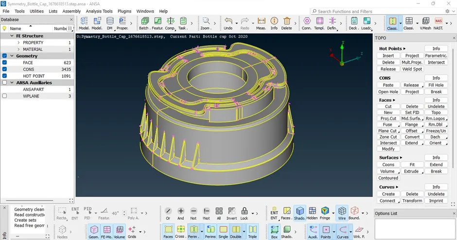
Raw CAD Model
Procedure:
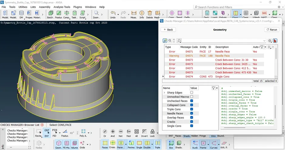
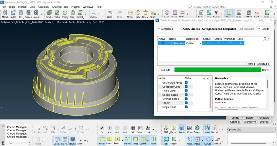
first import the model. Utilizing the checks-geometry tool in the menu bar, check the geometry for any mistakes such as singlecon, needle faces, and crack surfaces. Select execute after which we should right-click to rectify any mistakes if we found.
CAD Model with Geometrical Error
Next, select Faces>Orient to alter the orientation of every face. This guarantees that the orientation of each face is the same.
CAD Model with No Geometrical Error
The following procedure is to separate each component's mid surfaces into their own property ids. By manually offsetting the surfaces of either face to the middle, mid surfaces are extracted. Utilizing the Measure tool from Utilities>Measure, the thickness of each component is first measured.
Utilizing the Measure tool from Utilities>Measure, the thickness of each component is first measured. All the geometry were discovered to different thickness. The following step is to select List>Properties>New to create properties. Property has thickness allocated to it.
After selecting all the surfaces on a face with the Offset tool (Faces>Offset), the mid surface is then taken out. After checking the direction and offsetting, the offset value is set at half the thickness. By selecting Faces>Set PID and assigning to the appropriate property, the property is now allocated to the extracted mid surface. For all the components, all mid surfaces are retrieved and given properties.
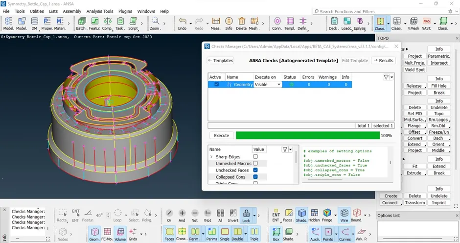
Once more, geometric defects are found in the extracted mid surfaces and corrected. Below is a display of the final extracted mid surfaces.
Mid Surface with No Error
Assigning Thickness to Each Face
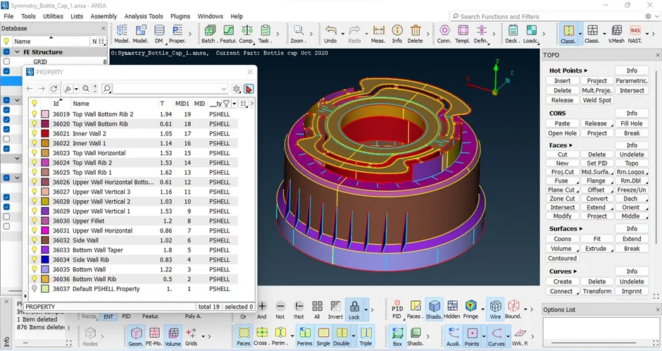
Then, select Utilities>Mesh Parameters to configure the mesh parameters. Target length, minimum element length, and maximum element length are set to 1, 0.5, and 3 in that case. For mixed and first order elements, all other parameters are left at their default values.
The next step is to configure the quality criteria by heading to Utilities>Quality Criteria. The quality criterion file is also stored for later use. The graphic below displays the parameters for the newly defined quality criteria.
Assigning Quality Criteria
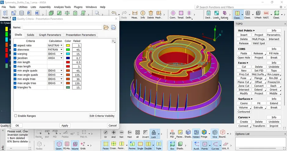
The mid surfaces must now be ready for meshing. Change to the Mesh module for that. By selecting all the CONS and entering 1 as the target element length value under Perimeters>Length, the shell element length is first changed. The same procedure is followed for all Macros (surfaces).
Then, the minimum element length is checked in every region, and any areas where elements would not meet the minimum length are changed.
The Mesh generation>Best tool is then used to mesh. The mesh is created by this tool using the best algorithm available.
Then, using the Shell Mesh>Reconstruct tool, the resulting mesh is polished. There are made sure there be no revolving quads. Trias are also kept to a minimum. The following needs to be ensured when working with trias.
No trias touching each other back-to-back or in the other direction
There are no trias around the edges.
On a feature, no trias
low number of trias in a given area
The following tools are utilized to deal with trias:
Grid>Paste the nodes in order to advance the tria backwards.
To split an element and advance a triangle, go to Elements>Split.
To rotate the tria left or right, select Elements>Swap.
Elements>to create a quad by joining two trias together.
The Shell Mesh>Smooth tool is used to improve the mesh's flow after modification. Any elements that don't meet the required standards are additionally corrected, either by remesh or by smoothing the elements. The produced mesh is displayed below.
Final Model
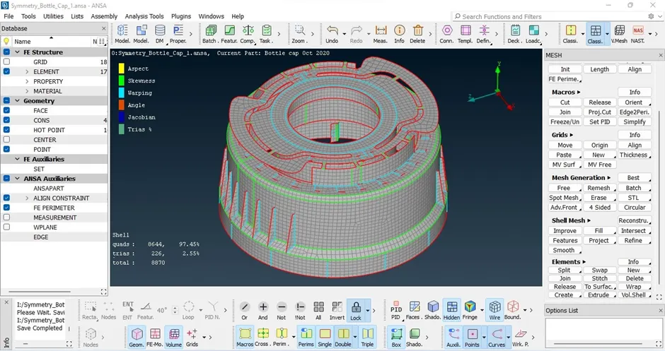
Learning outcomes
The trias cannot be totally minimized since the Bottle cap model contains several curved components. This challenge taught me how to generate faces for missing places, how to verify the geometry for faults and rectify them, how to build faces for mid-surfaces using the Middle command in faces, and how to conduct topology on the model. Additionally, this task teaches you how to create mid-surfaces and assign properties, materials, and thickness for plastic components.
Conclusion
In order to conduct the 2D meshing of plastic components for a bottle cap model, a geometry with fine topology and mid-surfacing was created. After doing this, the model geometry is checked to ensure that it is mesh as quads. The trias are switched around and rebuilt. The model is then rendered as a solid. This brings the challenge to a close.