Week 3 - 2D meshing for Sheet metal
Objective: For the given Hood model, Take the mid surface after checking the geometrical errors and mesh the mid surface with the given element Quality criteria.
|
S.No |
Quality Criteria |
Value |
|
1 |
Target/Average length |
5 |
|
2 |
Minimum Length |
2 |
|
3 |
Maximum Length |
7 |
|
4 |
Aspect |
3 |
|
5 |
Warpage |
15 |
|
6 |
Skewness |
45 |
|
7 |
Jacobian |
0.7 |
|
8 |
Minimum Quad Angle |
45 |
|
9 |
Maximum Quad Angle |
135 |
|
10 |
Minimum Tria Angle |
30 |
|
11 |
Maximum Tria Angle |
120 |
|
10 |
Tria Percentage |
15 |
Cad model image
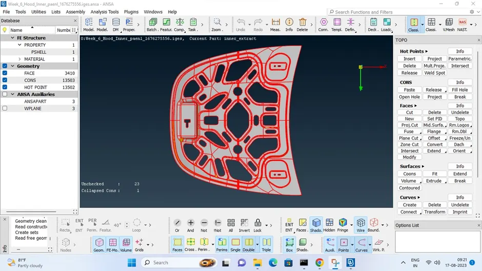
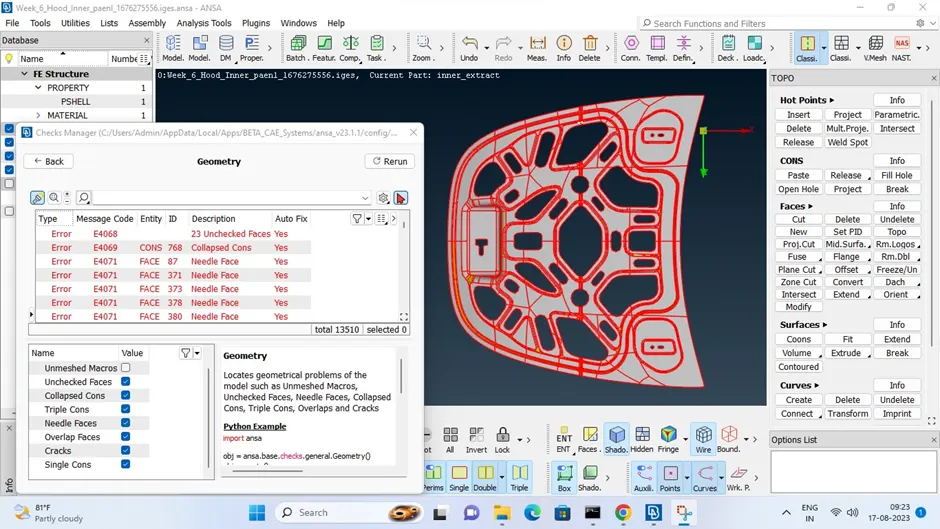
Given CAD model has been imported to ANSA and it has lot of geometrical error issues available in the CAD geometry. RAW CAD model and geometrical error are shown below.
RAW CAD Model
<!--[endif]-->
RAW CAD Model with Geometrical Errors
<!--[endif]-->
Procedure:
The above CAD model has geometrical errors like Unchecked Faces, Collapsed Cons, Trible Cons, Needle Faces, Overlap Faces, Cracks, and Single Cons.
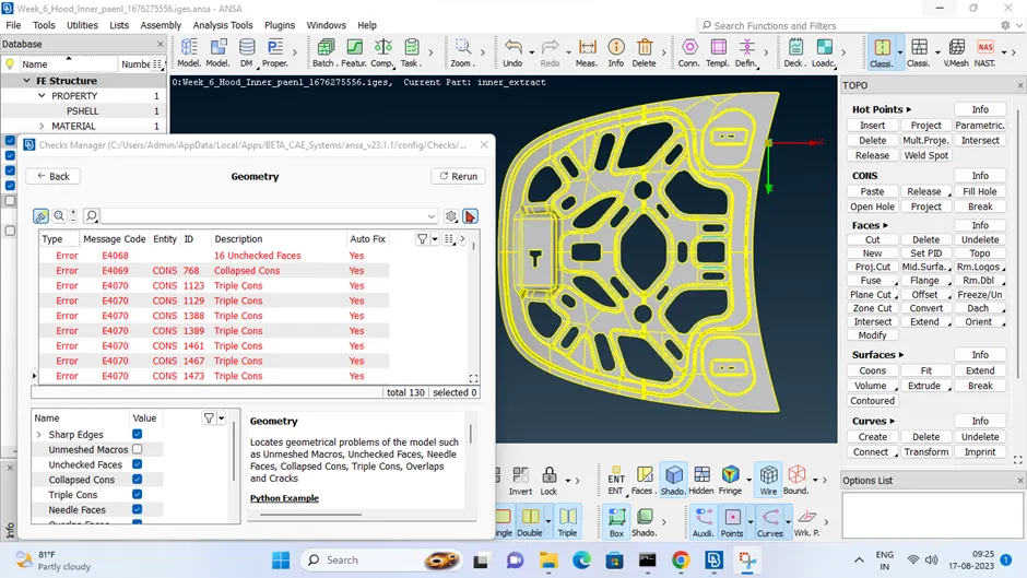
So, we have to do a geometry cleanup to remove the above errors and then we proceed to mid surface extraction. First we have to do Topo for that go to Faces>Topo tool is used for all the edges of each component at once to guarantee that all the surfaces are joined correctly. The next step is to run the geometry check for the parameters as shown in the image below by selecting Checks>Geometry. The faults found are shown in a different image.
Refined CAD Model with Geometrical Errors
<!--[endif]-->
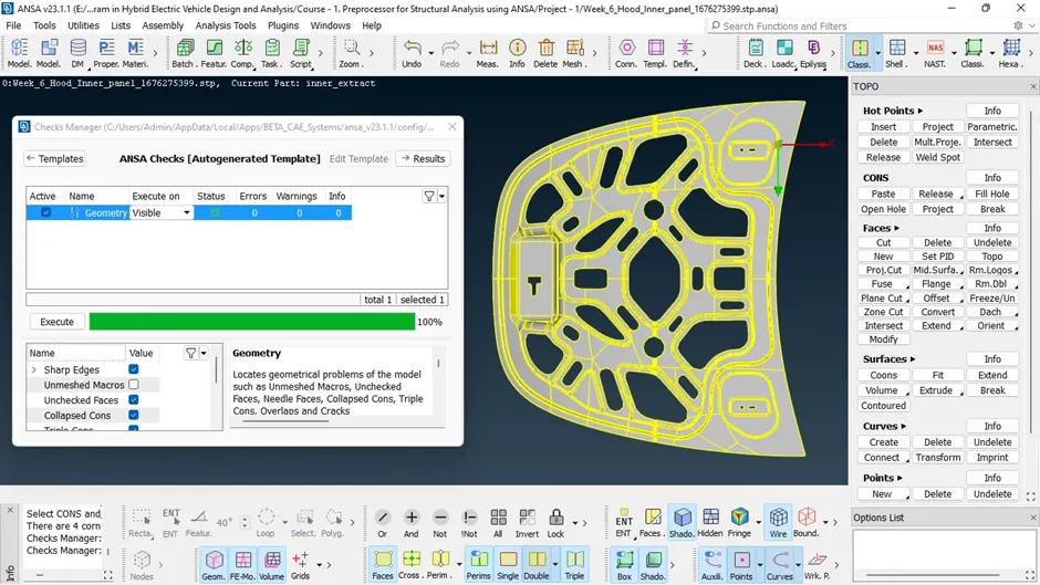
By right-clicking the problem and selecting "Fix," the majority of the errors were immediately corrected and few errors are corrected by manually.
Refined CAD Model with No Geometrical Errors
<!--[endif]-->
Next, select Faces>Orient to alter the orientation of every face. This guarantees that the orientation of each face is the same.
The following procedure is to separate each component's mid surfaces into their own property ids. By manually offsetting the surfaces of either face to the middle, mid surfaces are extracted. Utilizing the Measure tool from Utilities>Measure, the thickness of each component is first measured. All the geometry were discovered to be 0.75mm thick. The thickness is constant throughout the component because they are sheet metal parts. The following step is to select List>Properties>New to create properties. Property has thickness allocated to it, and property has a Material named "MS" generated and assigned to it.
After selecting all the surfaces on a face with the Offset tool (Faces>Offset), the mid surface is then taken out. After checking the direction and offsetting, the offset value is set at half the thickness. By selecting Faces>Set PID and assigning to the appropriate property, the property is now allocated to the extracted mid surface. For all the components, all mid surfaces are retrieved and given properties.
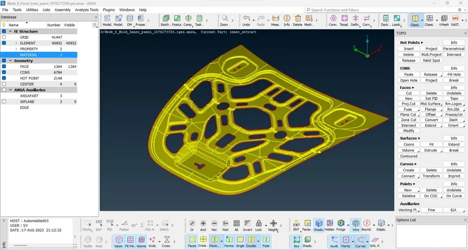
Once more, geometric defects are found in the extracted mid surfaces and corrected. Below is a display of the final extracted mid surfaces.
Mid Surface of CAD Model with No Geometrical Errors
<!--[endif]-->
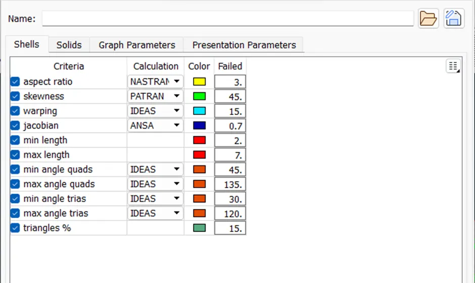
Then, select Utilities>Mesh Parameters to configure the mesh parameters. Target length, minimum element length, and maximum element length are set to 5, 2, and 7 in that case. For mixed and first order elements, all other parameters are left at their default values.
The next step is to configure the quality criteria by heading to Utilities>Quality Criteria. The quality criterion file is also stored for later use. The graphic below displays the parameters for the newly defined quality criteria.
<!--[endif]-->
The mid surfaces must now be ready for meshing. Change to the Mesh module for that. By selecting all the CONS and entering 5 as the target element length value under Perimeters>Length, the shell element length is first changed. The same procedure is followed for all Macros (surfaces).
Then, the minimum element length is checked in every region, and any areas where elements would not meet the minimum length are changed. Similarly, by combining the surfaces with the Macros>Join tool, CONS that are not necessary to define a feature are eliminated.
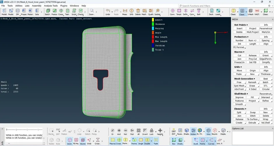
The Mesh generation>Best tool is then used to mesh. The mesh is created by this tool using the best algorithm available. Then, using the Shell Mesh>Reconstruct tool, the resulting mesh is polished. There are made sure there be no revolving quads. Trias are also kept to a minimum. The following needs to be ensured when working with trias.
<!--[endif]-->
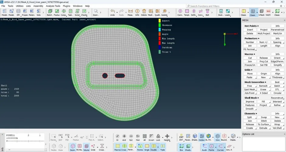
The Shell Mesh>Smooth tool is used to improve the mesh's flow after modification. Any elements that don't meet the required standards are additionally corrected, either by remesh or by smoothing the elements. The produced mesh is displayed below.
<!--[endif]-->
By selecting Utilities>Transform>Copy, the mesh is then mirrored for the outer panel, inner panel, and hinges after being created and passing quality standards. Using the mirror 3 points plane option, all the entities that need to be mirrored are first selected. Then, by switching to the Topo module, the mesh is examined for equivalence. If there are any free CONS, they are removed from the model and pasted using the Topo tool. The mesh is once more examined for quality standards. Finally, the "Draw shell as solid" option can be enabled by heading to Utilities>Quality Criteria>Presentation parameters and changing the representation of the shell element.
Results
The given hood model's geometry cleanup, mid surface extraction, and 2D meshing were all completed successfully. Additionally, every component meets the quality standards. The model accurately captures every feature with superb mesh flow. Low tria concentration is maintained.
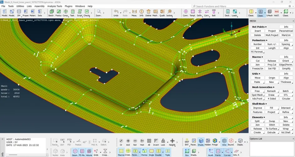
<!--[endif]-->
Final Model Image 1
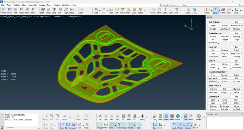
<!--[endif]-->
Final Model Image 2
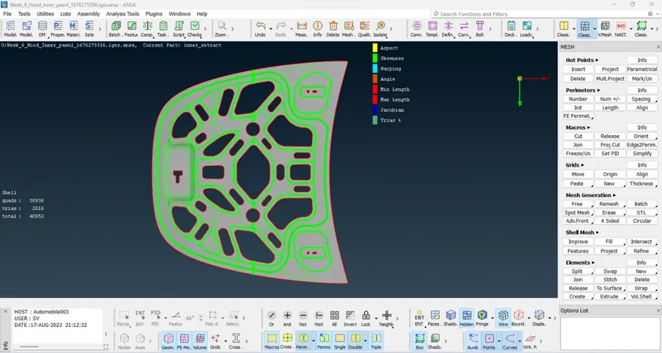
<!--[endif]-->
Learning Outcomes
Basic ANSA Software tools and GUI learning outcomes are to clear up simple component geometry and to assign an attribute and thickness to the mid-surface. Finally mesh the component and it should meet the Quality Criteria with improved mesh flow and reduced trias concentration..