Week - 4 - 2D meshing for Plastic components
AIM:
The aim of this project is to generate a proper mesh flow of a plastic component by following geometry clean-up, mid surface extraction and then meshing of the component using the tool ANSA pre-processor.
Objective:
The main objectives of the project as follows,
- To import and analyse the given CAD part of plastic bottle CAP and to perform geometry clean-up.
- To extract the mid-surface from the component manually.
- To assign varying thickness to the mid-surface extracted.
- To generate proper mesh flow from the mid part by qualifying following Quality criteria.
|
S.No |
Quality Criteria |
Value |
|
1 |
Target/Average length |
1 |
|
2 |
Minimum Length |
0.5 |
|
3 |
Maximum Length |
3 |
|
4 |
Aspect |
3 |
|
5 |
Warpage |
15 |
|
6 |
Skewness |
45 |
|
7 |
Jacobian |
0.7 |
|
8 |
Minimum Quad Angle |
45 |
|
9 |
Maximum Quad Angle |
135 |
|
10 |
Minimum Tria Angle |
30 |
|
11 |
Maximum Tria Angle |
120 |
|
12 |
Tria Percentage |
15 |
The generation of high quality meshes is of paramount importance for accurate simulations . In this project, from the face to face the component meshed manually using the ANSA tool which generates different types of structured and unstructured meshes in the component.
This approach consists of following methodology to develop complete mesh flow.
- Import CAD model
- Geometry clean up
- Mid-surface Extraction
- Shell Meshing
- Element quality check and Shell/solid mesh improvement
STEP 1: Import CAD Model
From the given task, the plastic component in IGES file format is imported first into ANSA from File > Open.
In order to generate a complete FEM, the very first step is to do geometry clean up to eliminate cracked & unwanted faces, single & triple cons over the surfaces and we need to make sure that the component if free from any topological errors.
After importing the model, It is found that there are some discrepancies in the geometry with many cracked and undefined faces. Before processing further, we need to stitch these faces using TOPO command from Faces > Topo and then select all with left click and then middle click. The CAD file is read and topology is applied, we can see many single cons are converted to double cons and then to refine the perimeter and macro of the component, changed the length to 1mm by switching to the module Classic mesh and then using command Perimeters > Length > perimeters/macros. Also using “FINE” tool we can finetune the model further more from the collapsed model as shown below.
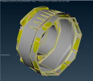
Fig.1 Before Topology
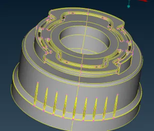
Fig.2 After Topology
You can now view the faces in Gray and yellow (as you are always in ENT view mode). Gray color represents the positive side of the faces while Yellow the negative side.
The orientation is currently random. There is not a uniform Face orientation. To activate the Faces>Orient> [Visible] function. The orientation of all the visible Faces becomes uniform now.
STEP 2: Geometry Clean-up
The next step involves checking for any geometrical error in the given component using the tool “Checks > Geometry” this option locates geometrical problems of the model such as unmeshed macros, unchecked & cracked faces, Needle faces, collapsed cons, triple cons and other overlap faces.
The Checks Manager window opens. Here you can select the type of problems that may exist in the geometry of the model to be investigated by activating the corresponding flag in the lower part of the window.
Keep the default options and click Execute
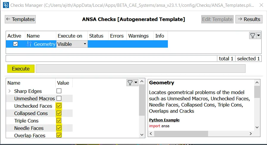
Fig.3 Check geometry manager
Using check geometry found lots of issues like sharp edges, cracks and geometry inconsistent.
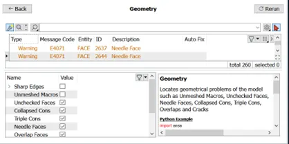
Fig.4 Check geometry results
There are two ways to resolve the errors while doing geometry check,
- By using Auto fix option where majority of the errors can be cleared automatically by ANSA.
- By manual fix, where user need to identify the specific error and isolate it on the screen by right-clicking on it and selecting “Show only”.
Depending on the type of the problem ANSA also offers the option to automatically fix it. In this model, I tried to fix most of the errors by right clicking the errors and then “FIX”. Some needle faces and missed faces are manually updated and cleared all the errors by doing geometry check again with 100% error free model.
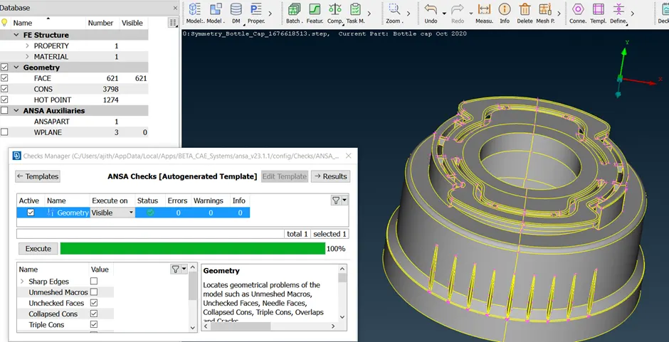
Fig.5 Check geometry results with "Zero" error
Next, to find the thickness, since it is a plastic component there are many variable thicknesses around the component.
Checked and marked the thickness around the component using command Utilities > Measure and found each and every part having different thickness and needs to be approached in manual way to offset the mid surface.\
STEP 3: Mid-surface extraction
In ANSA, generally for casting & molding products we always go with Solid meshing.
Even though the current plastic model has variable thickness, I tried to do casting for the component to extract the mid-surface by using command Faces > Mid-surfacing > Casting and updated the parameters as below.
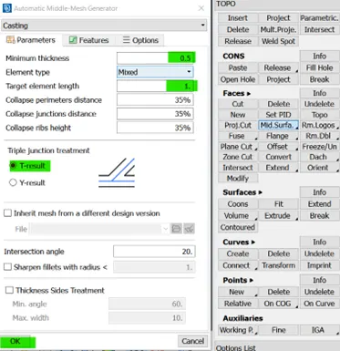
Fig.6 Casting window
Mid surface casting not worked since there is inconsistent in Mid surface creation, so I choose to do manual offset as below using commands Offset & Middle
Mid surfaceing using Middle command:
For the 2 inner ribs, we will be using the Faces > Middle >Multi command. In this command, we provide two side surfaces (RED & GREEN for inner and outer area) and one surface that represents the thickness of the feature (BLUE) and ANSA will automatically generate a mid-surface for that feature as below.
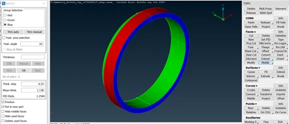
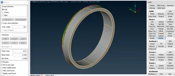
Fig.7 & 8 Mid surface extraction using command "Middle"
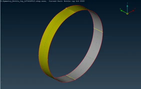
Fig.9 Mid surface of inner wall
Mid surfaceing using Offset command:
For the bottomm plane area, used command Offset > Faces and then applied offset value of the measured thickness as below.
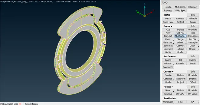
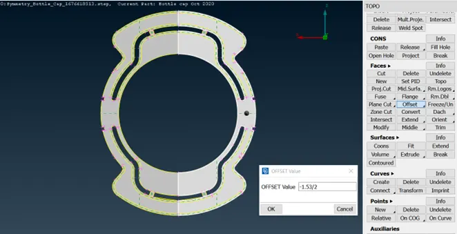
Fig.10 & 11 Mid surface extraction using command "Offset"
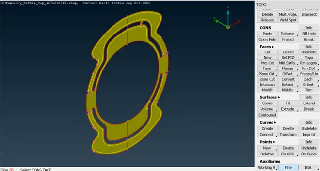
Fig.12 Mid surface of bottom plane surface
Some of the critical areas of the component are extracted as follows:
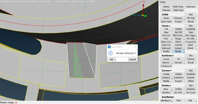
Fig.13 Mid surface creation using command Middle > Single
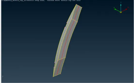
Fig.14 Mid surface creation of Inner Rib with command Middle > Single
For the section with varying thickness like below side barriers, we need to create the mid surface manually with the actual projections in it. So we can assign the exact thickness to the surface.
First using "NOT" option you can select the rquired area to be isolated, once it is suppressed right away if you click "Invert" option from Focus tools, you can isolate the required section as below.

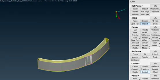
Fig 15. CONS projection of side wall
And then I tried to project the vertical lines from one surface to another surface from CONS > Project, by which I can create exact section of mid surface easily to assign variable thickness. Next by using Middle command , created mid surface for the part of the component at each side of the plastic cap.
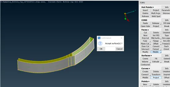
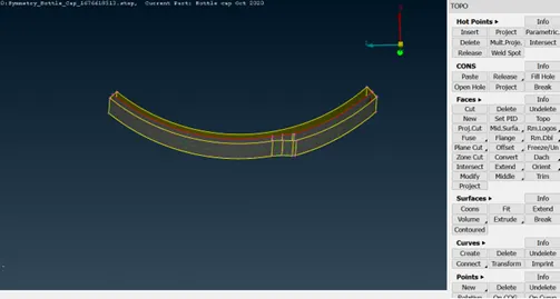
Fig 16 & 17 Mid surface extraction of side wall
Next for the mid surface of inner teeth, we take the offset of one tooth and copy that mid surface to all the remaining teeth using the Transform > Copy command.
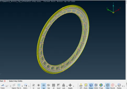
Fig 18. Isolating Inner teeth feature
The steps to do so are as follows:
- Generate mid surface of one tooth
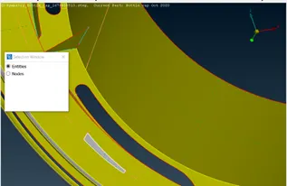
Fig 19. Selecting tooth mis-surface
- Create 2 COG points away from each other by referencing the nearest curves.
- Use the Transform > Copy command to Rotate/Copy the mid-surface by taking 2 COG points as centre of axis.
- Provide number of teeth and spacing angle for each tooth (In this case it is 360/26)
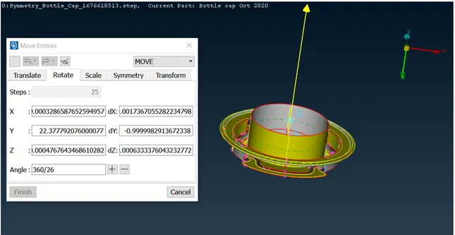
Fig.20 ceating axis of rotation
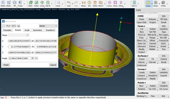
Fig.21 Teeth profile creation
Now the teeth features are extracted successfully and by using the same method we can generate the mid-surface of inner bottom features also.
For below teeth profile, to get the proper mid area we need to project the cons from one surface to another as it is having variable thickness.
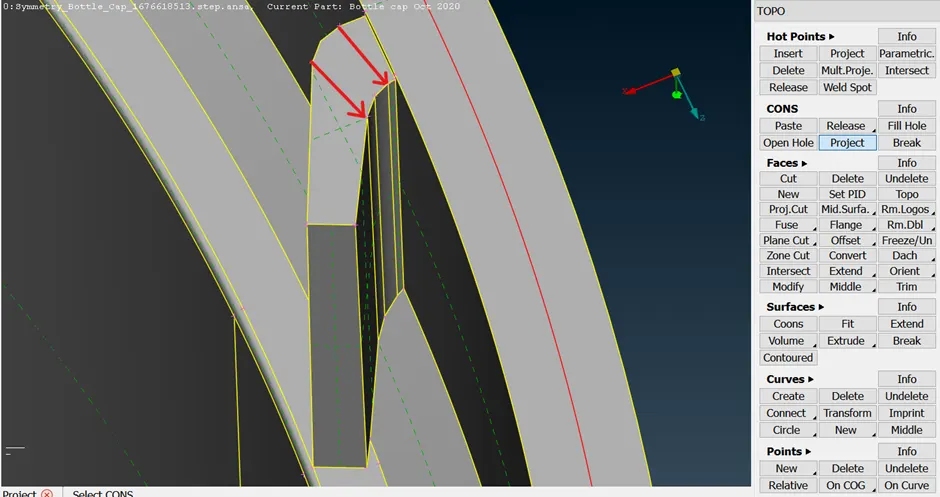
Fig.22 Inner Teeth profile creation
Then using command Curves > Middle, create a curve in between the two surfaces on both the ends.
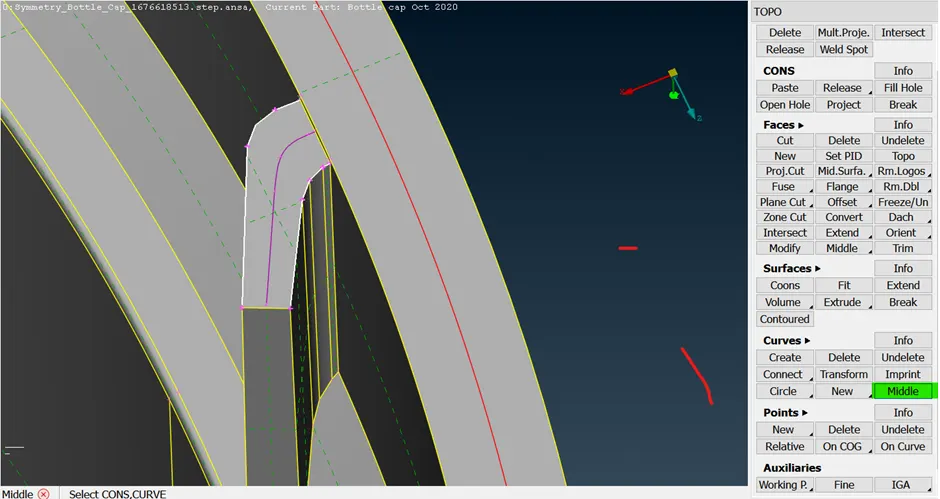
Fig.23 Inner Teeth profile curve creation
With the command Faces > new created a new face by connecting the two curves as below
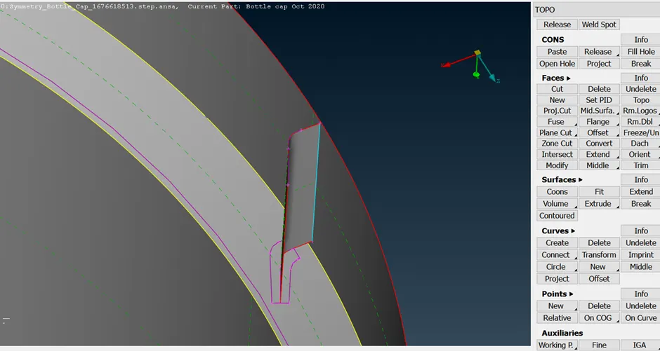
Fig.24 Inner Teeth profile mid-surface creation
Now, with the previous feature command, selected the entity of single face and using Rotate command, copied into multiple entities in total of 12 faces as below.
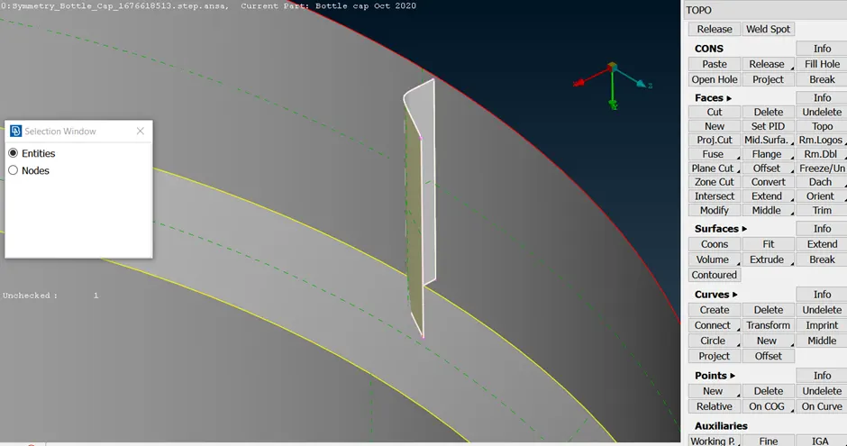
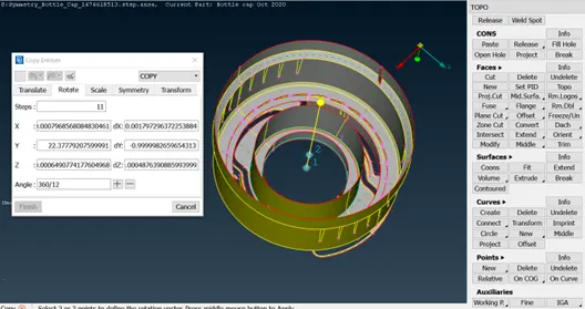
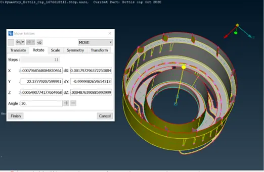
Fig.25, 26 & 27 Inner Teeth profile mid-surface creation
Any unwanted faces are removed using command "TRIM" and "Intersect" option to join and cut the mid-surfaces each other.
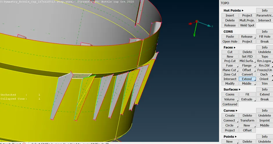
Fig.28 Outer rib profile extention
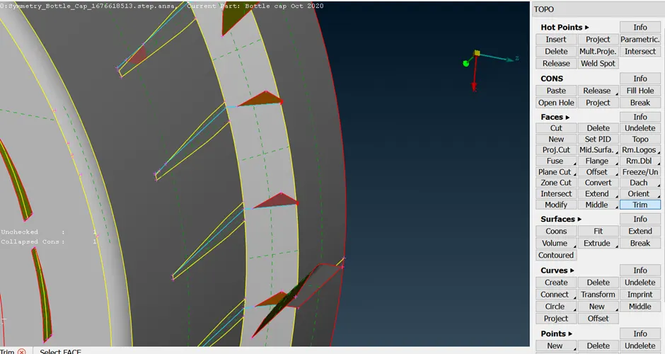
Fig.29 TRIM feature
STEP 4: Shell meshing - Uniform size mesh
Before meshing any component, two things we need to follow,
- To assign proper thickness to the mid surface extracted. Since we followed manual approach to create mid-surface, ANSA won't assign thickness automatically. we must assign PID to each mid surface with the measured thickness already.
- Applying quality parameters. Every product which is been produced will go through the set of quality check. If quality fails, applying loads will not be feasible and result will be not accurate enough to analyse the product. So element quality check should be always performed.
For the extracted surface, created new PSHELL property for each and every surface with noticng colors to it. The colrs represents the different PID's were assigned to different surfaces with varying thickness around the component.
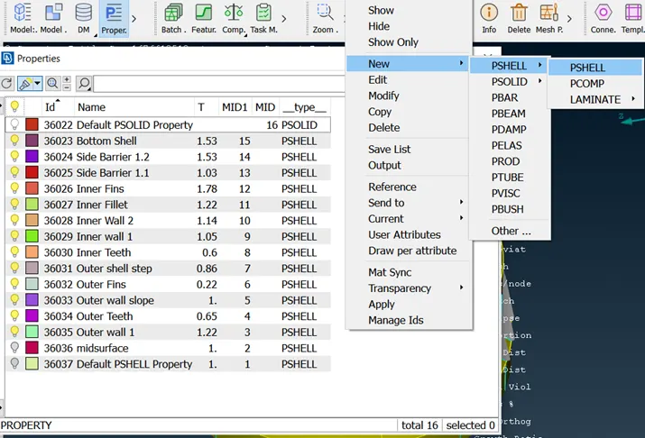
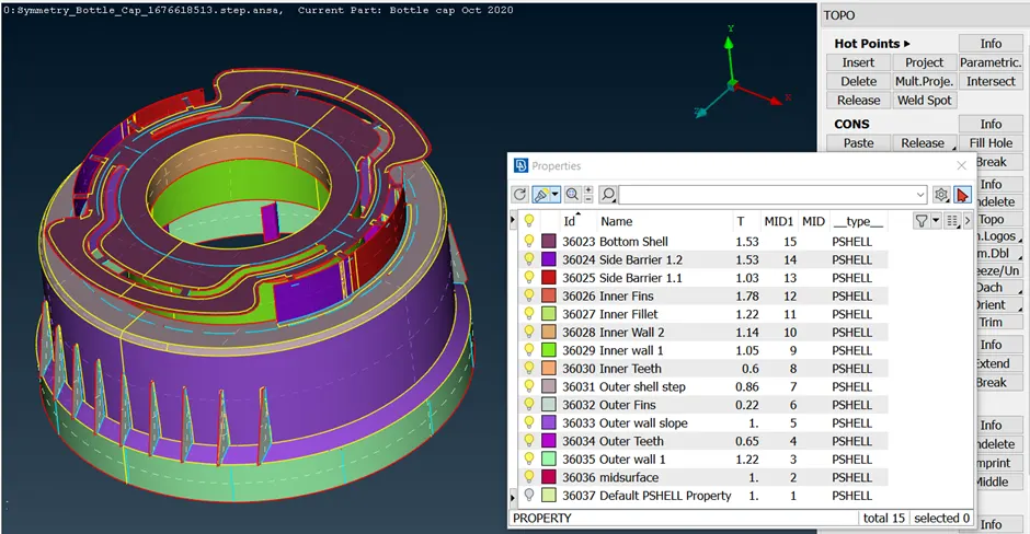
Fig.30 & 31 set PID's
Secondly, I set the quality criteria for the component as per given criteria for this project as below by using shorkey "F11", where updated parameters as per given quality criteria mentioned initially and then presentation parameters in which Element % is checked and dragged the demand effect to more details , then "Apply" and click "Ok".
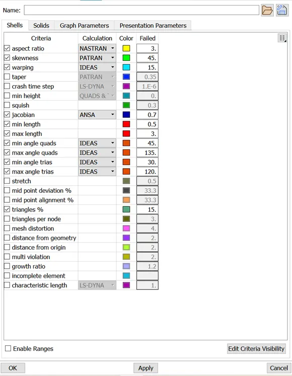
Fig.32 Assigning Quality Criteria
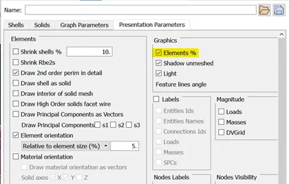
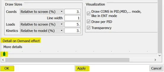
Fig.33 Assigning Quality Criteria
Once assigning the quality value mesh parameters has to be set by moving to the window Utilities > Mesh parameters and then set Target length as 1mm. Also we can save this settings in local folder for our future references.
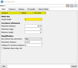
Fig.34 Assigning Mesh Parameters
And the very next step in the mesh module, as per given quality criteria. I refined the geometry parameters and macro to "1mm" by following command Perimeters > Length > Perimeters/Macros.
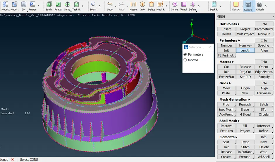
Fig.35 Perimeter change
Now, we come to the part of shell meshing, where below the steps need to be followed.
Step 1: To generate mesh - GO to Mesh generation > best > select the surfaces to be meshed & middle click the mouse to confirm. Now the mesh will be generated on the selected surfaces.
Step 2: Quality check - To get visibility of quality failure. Go to hidden mode from shadow mode.

Here you find the highlights of errors with respect to the given quality parameters early. we can hide the inactive parameters by simpy right clicking and then select "hide inactive criteria".
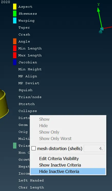
Fig.36 Checking Quality Criteria
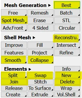
Step 3: If any elements fails for quality then play with shell mesh tab (Resconstruct & Smooth option), Elements tab (Split, Join, Swap option), Grids tab (Move & paste option) to meet the quality criteria. Those option will mostly helps to resolve the quality failure of the elements. Some of the examples for the above mentioned options used in this projects are represented with a picture below.
Step 4: Elimination of trias - Mostly the trias should be eliminated whereever possible.
- Two opposite trias should be eliminated.
- Tria element should not lies on perimeter line.
- Nearer trias must carried out to some extent.
- To achieve above three points in step 4. Split, swap, join, paste options can be used.
At Final, the mid component extracted is meshed successfully and acheived with low tria concentration (1.82%) and (98.18%) Quad elements as shown below.
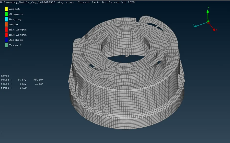
Fig.37 Final profile with proper mesh flow
Draw Shell as Solid:
Draw shell as a solid should be activated as a part of the challenge before completing the task. Since it is a shell element, after activating draw shell as solid the meshed elements will convert to solid by considering the thickness already assigned manually on PID's.
To do this, go to Quality criteria (can use shortkey "F11") > Presentation parameters > Select Draw shell as solid > Ok and then we achieved solid mesh elements as below.
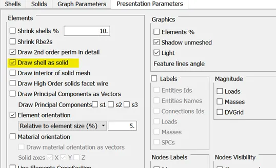
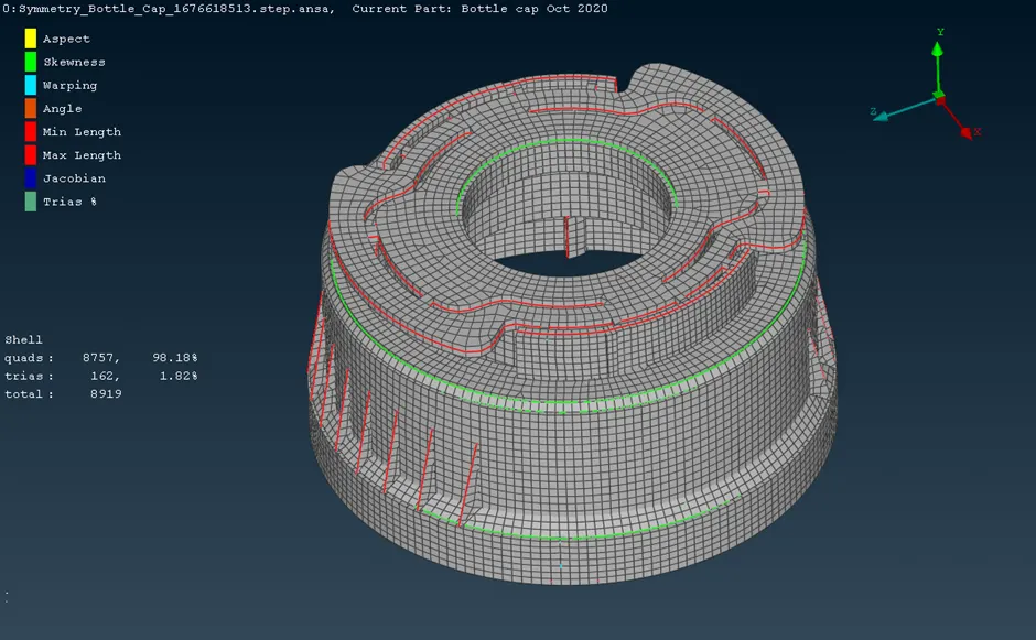
Fig.38 Solid profile of meshed elements
Learning Outcomes:
At the end of the challenge, I can able to,
- Perform geometry clean-up for any complex plastic model with added features.
- Generate mid-surface manually for any complex part.
- Proper mesh flow throughout any component which meets the given quality criteria.
- Improve mesh quality by identifying any failure mesh elements.
- To work on ANSA more fluently .
CONCLUSION:
Hence the mid-surface of the component extracted manually with all the features captured properly by following geometry clean-up, and then meshing of the component using the tool ANSA BETA CAE which passed all the quality parameters from the assigned task. The plastic bottle cap is finally meshed in a proper flow with tia percentage of 1.82% have been achieved.