Week - 4 - 2D meshing for Plastic components
AIM: 1.To clean up the given geometry and generate mid surface for the same.
2. To assign PIDs to midsurface entities of same thickness and also assign them with their corresponding parent geometry thickness.
3. To generate a good mesh flow for the generated mid surface with the following criteria:
Target/Average Length 1
Minimum Length 0.5
Maximum Length 3
Aspect 3
Warpage 15
Skewness 45
Jacobian 0.7
Minimum Quad Angle 45
Maximum Quad Angle 135
Minimum Tria Angle 30
Maximum Tria Angle 120
Tria Percentage 15
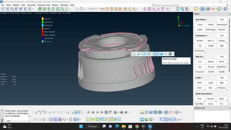
4. To activate "draw shell as solid" after successful generation of mesh.
PROCEDURE:
1. The model "bottle cap.ansa is downloaded.
2. A quick geometry check is run to check for errors in the parent geometry. Only a few needle face errors are found which are auto fixed.
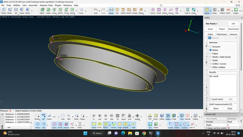
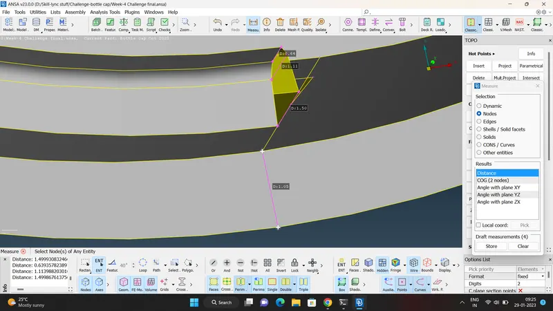
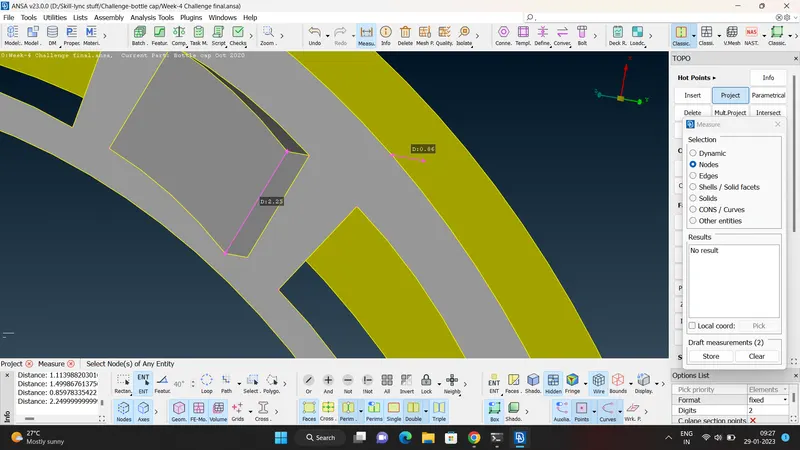
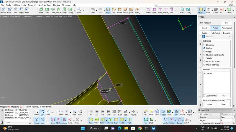
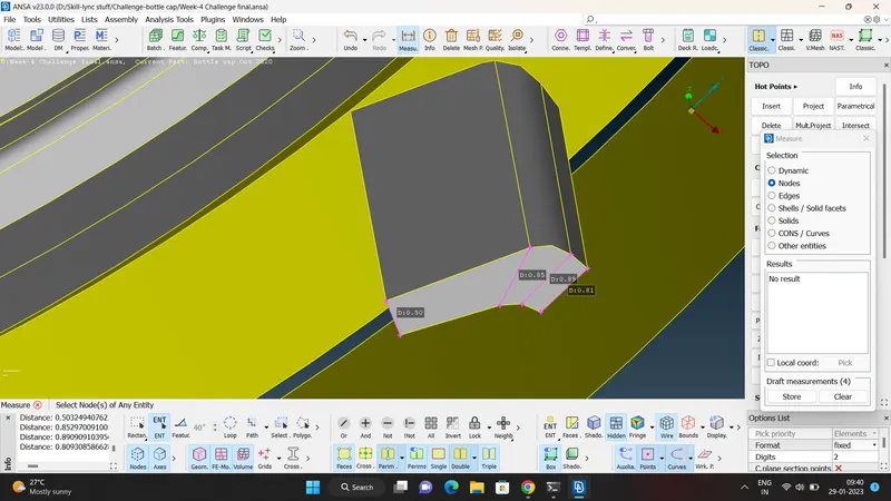
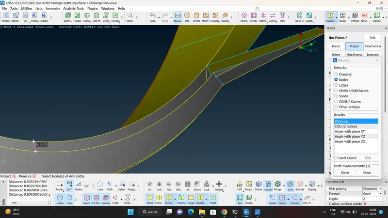
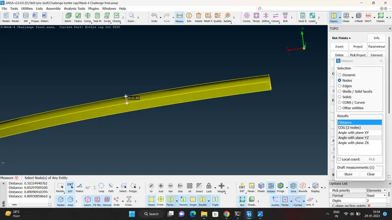
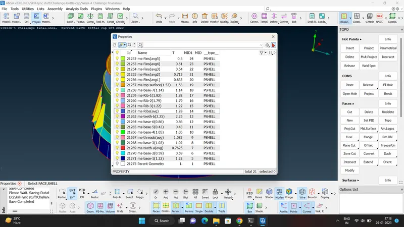
3. Thickness is measured for all the entities. It is observed that the thickness varies in the same entity in case of Fins, Ribs, Threads and Teeth-a, as mentioned in the properties tab in the attached ansa file.
In this case, an average value of the corresponding varying thicknesses is taken and assigned to the mid surface entity extracted.
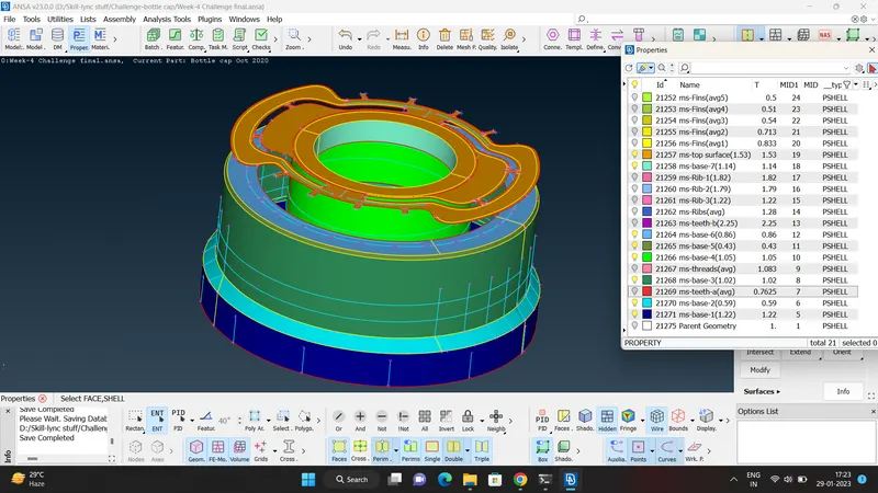
Screenshots corresponding to the nodes where the thicknesses for all the parent geometry entities have been taken from are attached below.
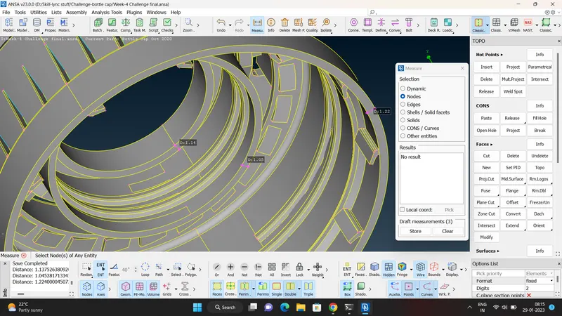
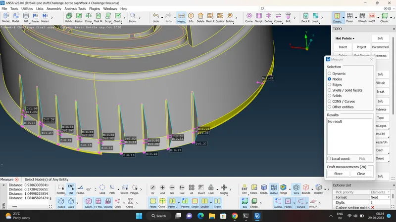
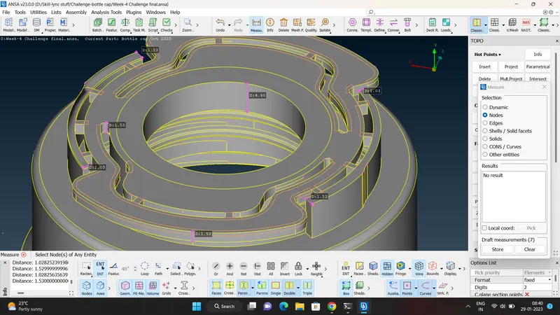
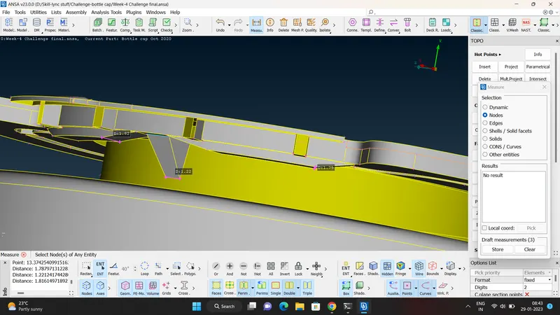
4. Mid surface extraction is started with the large cylindrical base surfaces. Here these entities are named as base surfaces 1-7. Each entity has a different thickness. All these surfaces including the top surface have been extracted using the "OFFSET" command because of their simple geometry and constant thickness.
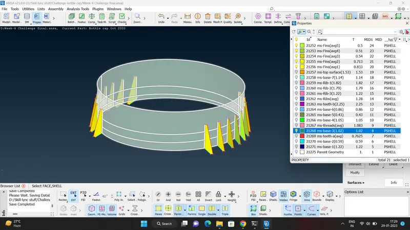
5. Mid surfaces for the nearly triangular fins have been extracted using a combination of "Curves-->Middle", "Faces-->New-->COONS" and "Faces-->Extend" commands. It is observed that there are 18 fins in total divided into 5 sets of average thicknesses. Avg 1-4 have 4 fins each lying symmetrically on the left and right side of the center fin and avg 5 has 2 center fins.
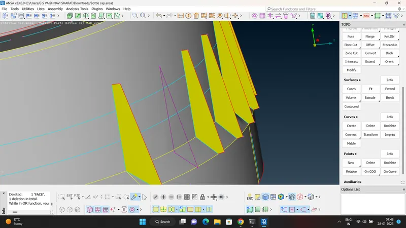
6. Mid surfaces for Rib-1, Rib-2, Rib-3 and teeth-b have been extracted using "Faces-->Middle-->Single" command.
In case of teeth-b, in the utilities tab, "Transform-->Rotate" command is used. First, the axis of rotation is defined by creating centres for two circles at different heights by using "Points-->On COG" command.
A total of 26 teeth-b are present. Since we have already generated mid surface for one tooth, we need to create 25 more entities around the axis at an angle spacing of 360/26=13.85degrees. This is done by feeding the appropriate values to the tabs present in "Transform-->Rotate" command.
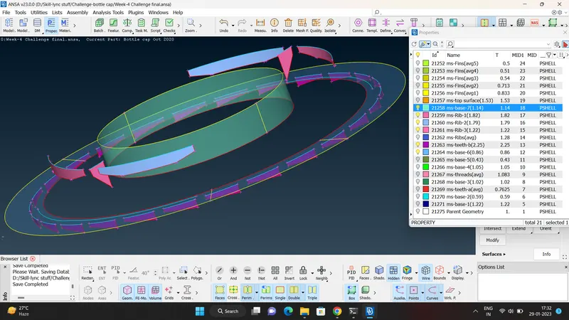
7. In case of threads, "Curves-->Middle" command is used. 2 threads have been spotted in the parent geometry. Both of them are found to have the same cross section and same thickness, hence they have been assigned to the same entity. Their middle curves are extracted accordingly and those curves are projected on to the corresponding base surfaces.
"Faces-->New-->COONS" command is used to generate the midsurface.
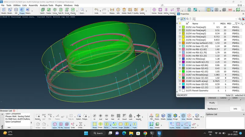
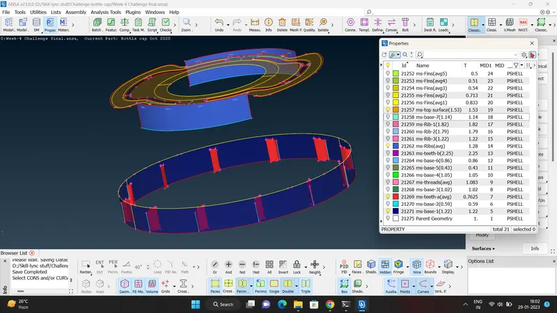
8. Mid surfaces for Ribs and Teeth-a have been extracted using "Curves-->Middle" and "Faces-->New-->COONS" commands. This is to cater for the varying thickness values across their cross sections and to generate a mid surface that can hold an average value of the corresponding thicknesses. Additionally, the "Transform-->Rotate" command is used for teeth-a with the following inputs.
Number of teeth-a present in the parent geometry are 12. We have already extracted mid surface for one tooth, we need 11 more at an angle spacing of 360/12=30degrees. The axis of rotation is defined by creating centred for two circles at different heights using "Points-->On COG" command. Rotate command is applied for these inputs on teeth-a to obtain a results as shown below in the image.
9. All the generated mid surfaces are joined with one another in accordance with the parent geometry by using "Faces-->Extend" and "Faces-->Intersect" commands. Triple Cons are found to exist in the mid surface component as there are certain areas where 3 surfaces meet. It is not considered an error.
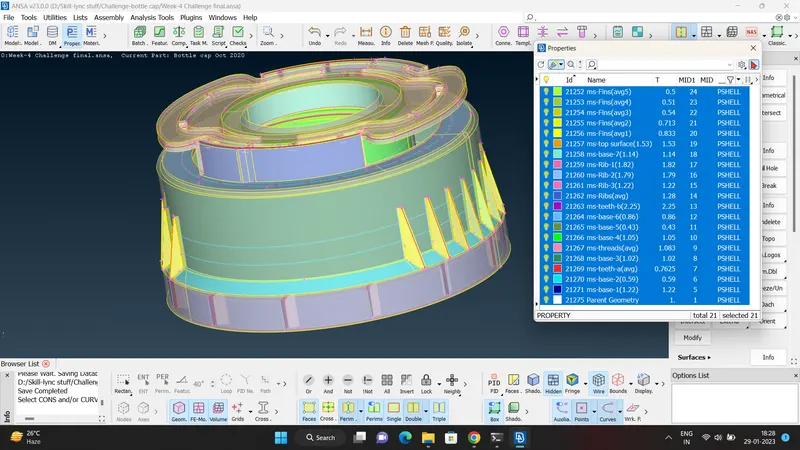
10. By using the "Faces-->Set PID" command, same thickness entities are assigned to the same property. They are then assigned with the thickness of the corresponding parent geometry part.
The mid surfaces and the entire parent geometry are shown below in the figure in the PID mode.
11. It is observed that there are some Cracked cons, collapsed cons, two surfaces not joined properly together. To rectify this, the entire base-1, base-2, base-3, fins, teeth-a are extracted again after deleting the entites with errors.
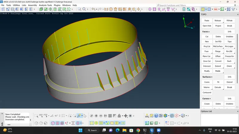
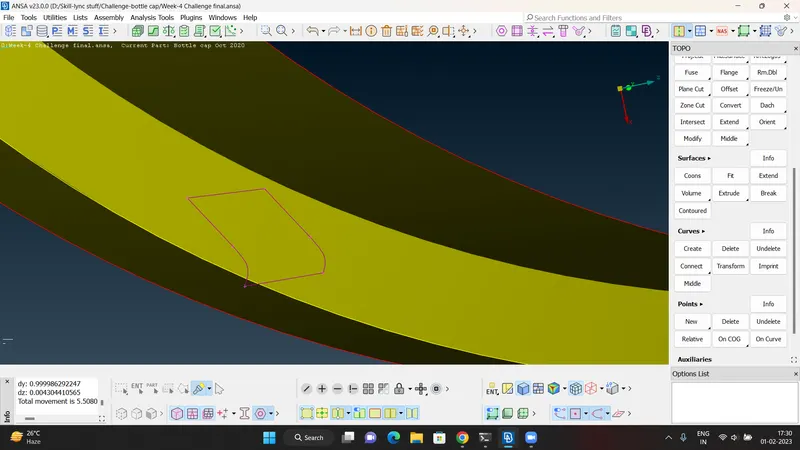
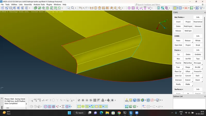
After checking the Module for errors, any collapsed cons or improper TOPO, it is prepared to be meshed. We switch to the mesh module, all the midsurface entities are selected and in "PERIMETERS-->LENGTH" the value is given as 1.
12. The mesh parameters and Quality Criteria are given accordingly. The corresponding values are saved as .ansa_mpar and .ansa_qual files.
13. The macros are prepared to be meshed by using Hot Points-->Insert, Perimeters-->Num+/-, Macros-->Cut, Macros-->Edge2Perim. commands.
14. Mesh is generated using Mesh Generation-->Best, Shell Mesh-->Reconstruct, Shell Mesh-->Smooth commands.
15. Trias and rotating quads are minimized or eliminated using Elements--Split, Grids-->Paste, Shell Mesh-->Collapse commands.
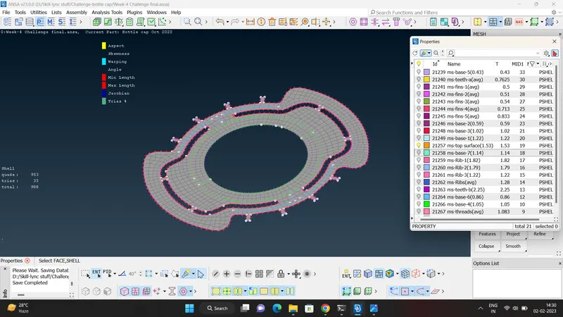
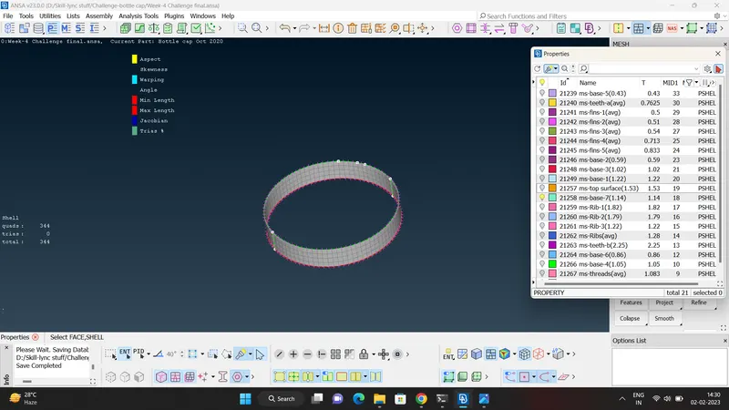
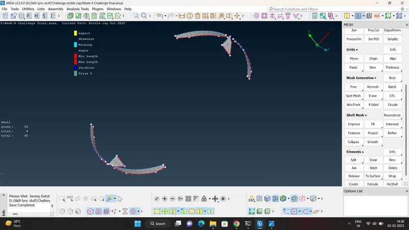
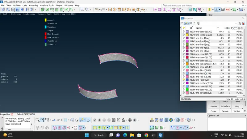
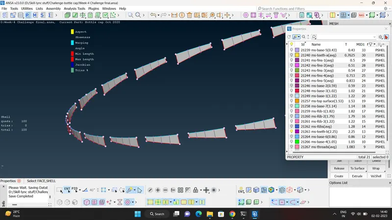
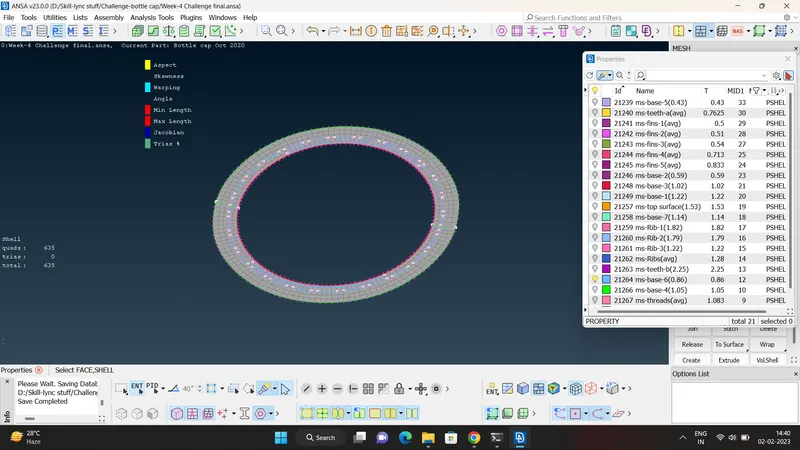
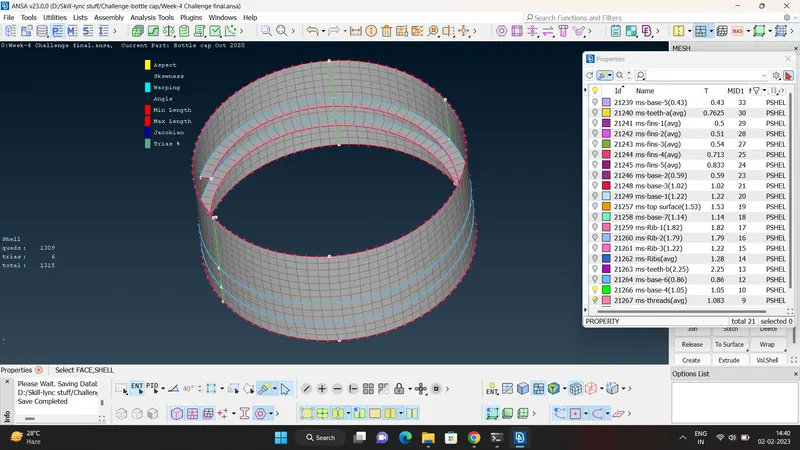
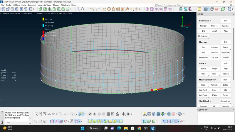
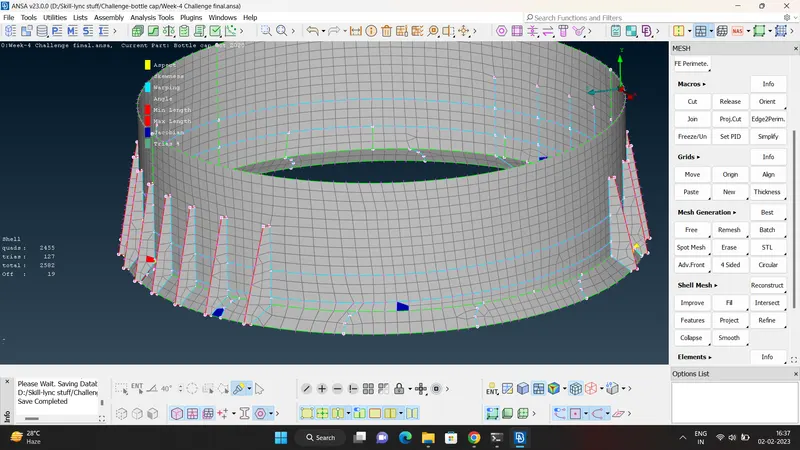
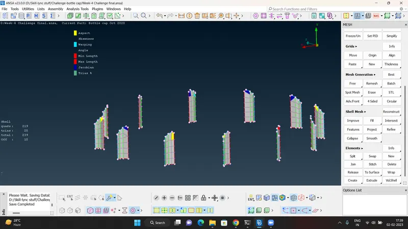
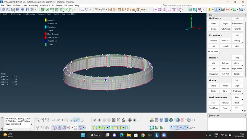
16. It is observed that elements are failing near the spots where triple cons are overlapping or where the threads are very close to the base. They are kept as it is as most of them cannot be fixed.
At the end, the module is meshed with a total of 39 off elements. In the Presentation Parameters, "Draw Shell As Solid" is enabled and the module is saved.
OUTCOMES:
1. Extraction of mid surface near a complicated area has been learnt successfully.
2. Use of Faces-->OFFSET, Curves-->Middle commands has been understood well and implemented correctly.
3. Use of Cons-->Project in areas where Faces-->Extend cannot provide desired surface has been done successfully.
4. Eliminating tria elements in surfaces with a neat cross section has been understood more clearly.
5. Choosing to accept certain trias where the geometry converges has been understood well.
6. Distinguishing between a good surface and an improper surface has been understood clearly. Methods to correct such surfaces have also been learnt.
7. Use of "Edge2Perim" command and "Join" in Macros has been learnt successfully.
8. Purpose of "Grids-->Origin" has been learnt and its importance has been understood.
9. Preparing a mid surface for entities with varying thickness has been understood.
10. Identifying elements of same thickness and assigining them to the same PID has been done sucessfully.
CONCLUSIONS:
1. It is inferred from the module that it is a good practice to extract the midsurface for the entire parent geometry and then assign the corresponding thickness values to it after meshing.
2. In order to generate a good mesh flow, surfaces must be connected appropriately, avoiding unnecessary cons and hotpoints. This would facilitate changes made in the later stages in the process of smoothening the mesh elements, especially in the immediate neighbouring areas.
IMPROVEMENTS TO BE MADE IN FUTURE:
1. Deciding upon which trias to accept, which off elements to accept is a new learning in this module. With practice on more modules, this can be improved.
2. The base-3 surface and base-2 surface can be done better by correcting some topo errors.
3. Time taken to generate the module can be reduced a lot with a good knowledge on the commands mentioned in the report and also in their order of implementation.