Week - 4 - 2D meshing for Plastic components
Meshing Of Plastic Components
Aim:
For the given Plastic Bottle Cap model, I am going to check for the geometrical errors and take the mid surface by suitable mid surfacing techniques and Mesh the same with the given element Quality criteria.
|
S.No |
Quality Criteria |
Value |
|
1 |
Target/Average length |
1 |
|
2 |
Minimum Length |
0.5 |
|
3 |
Maximum Length |
3 |
|
4 |
Aspect |
3 |
|
5 |
Warpage |
15 |
|
6 |
Skewness |
45 |
|
7 |
Jacobian |
0.7 |
|
8 |
Minimum Quad Angle |
45 |
|
9 |
Maximum Quad Angle |
135 |
|
10 |
Minimum Tria Angle |
30 |
|
11 |
Maximum Tria Angle |
120 |
|
12 |
Tria Percentage |
15 |
Procedure :
Step 1:
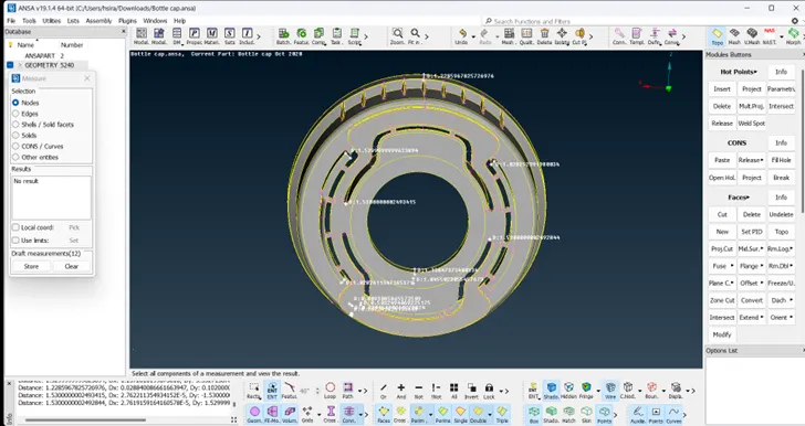
Open option under file is used to open the required cad file in ansa.
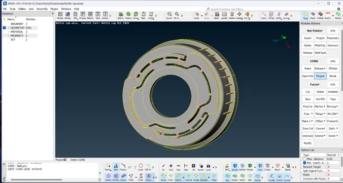
Measure option under utilities is selected for measuring the lenth between the cons.
Step 2:
Geometry option under checks is used to check the geometry errors in the given cad file.
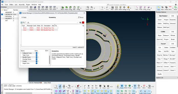
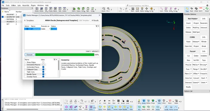
Auto fix option is used to solve the errors found in geometry check.
Step 3:
Offset option under faces is used to create the base mid surface for the given model.
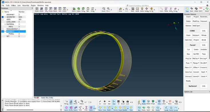
New option under faces is used to connect the two faces of the mid surface. Single cons are selected using new faces using cons and it create a double cons by connecting the to single cons.
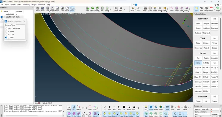
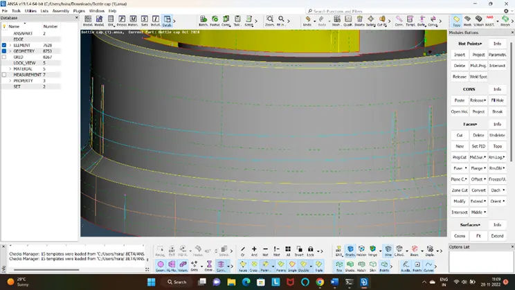
Step 4:
Middle option under curves is used to create a at the middle of two cons.
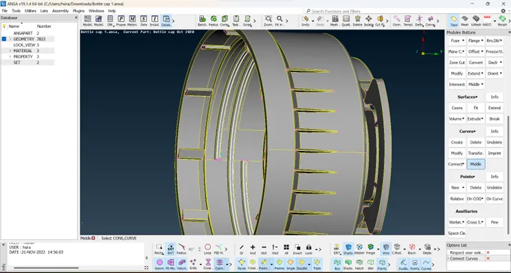
Fine option under auxiliaries is used to increase the resolution of the curve.
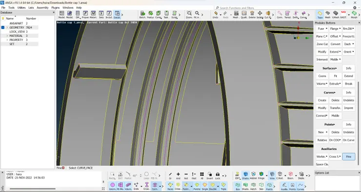
The curve is then projected over the base mid surface, a double con is created. By selecting the double con and curve a new face is generated.
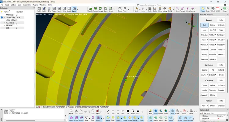
Step 5:
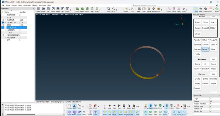
Middle option under faces is selected to generate the mid surface for the features.
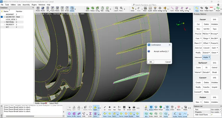
After the surface is generated for the features, it is then extended to the base mid surface using Extend option under the faces command.
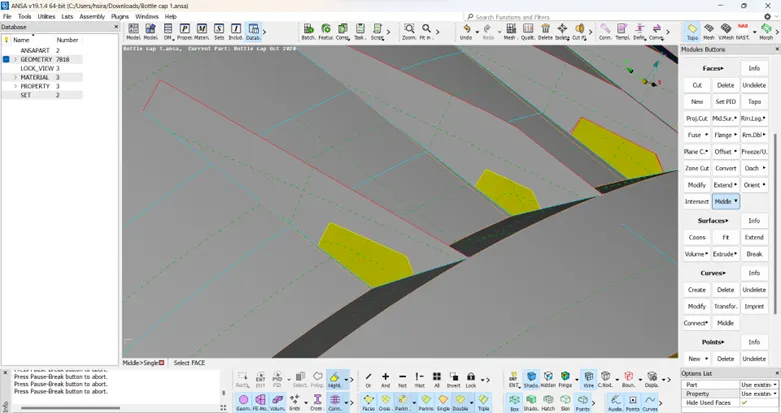
Step 6:
On COG option under points is selected, to create a centre point. Select two circular line one by one to create points one by one.
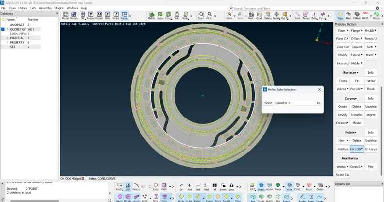
Middle option under curve is used to create a middle curve at the side face of the tooth.
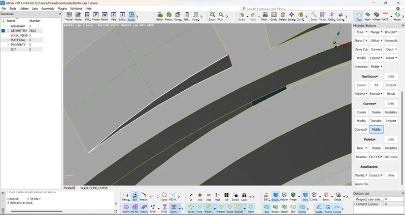
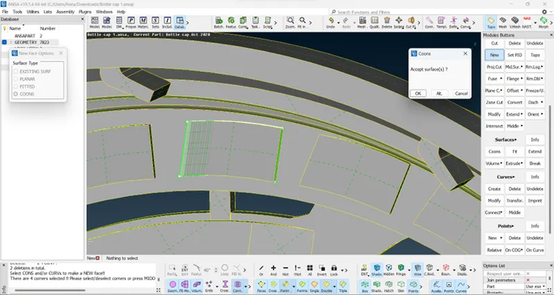
Create a surface by selecting the two curves, which will be the mid surface for the tooth.
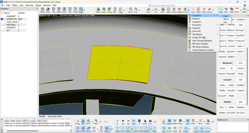
Copy option under transform is used to transform the generated mid surface to the other tooth.
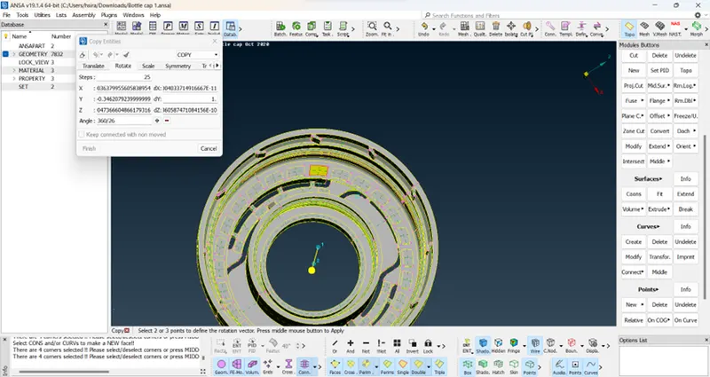
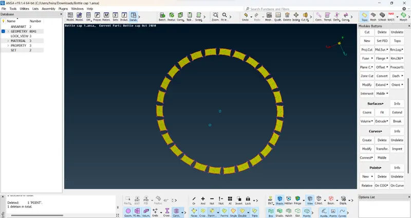
By repeating the above step mid surface for the features also obtained. Features mid surface is then extended to the base surface.
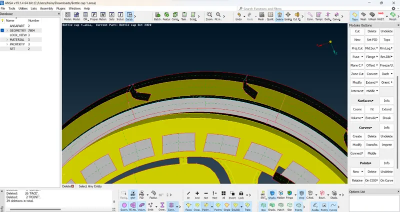
Step 7:
Switching to Mesh mode.
Step 8:
Mesh parameters option is used to set the parameter for the good mesh flow.
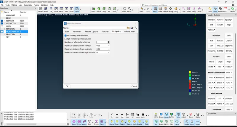
Step 9:
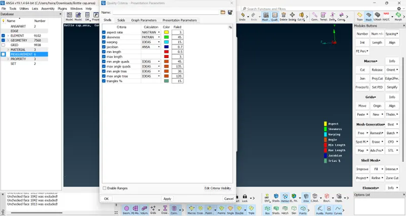
Quality Criteria option is used to fix the valve for the given criteria.
|
S.No |
Quality Criteria |
Value |
|
1 |
Target/Average length |
1 |
|
2 |
Minimum Length |
0.5 |
|
3 |
Maximum Length |
3 |
|
4 |
Aspect |
3 |
|
5 |
Warpage |
15 |
|
6 |
Skewness |
45 |
|
7 |
Jacobian |
0.7 |
|
8 |
Minimum Quad Angle |
45 |
|
9 |
Maximum Quad Angle |
135 |
|
10 |
Minimum Tria Angle |
30 |
|
11 |
Maximum Tria Angle |
120 |
|
12 |
Tria Percentage |
15 |
Step 10:
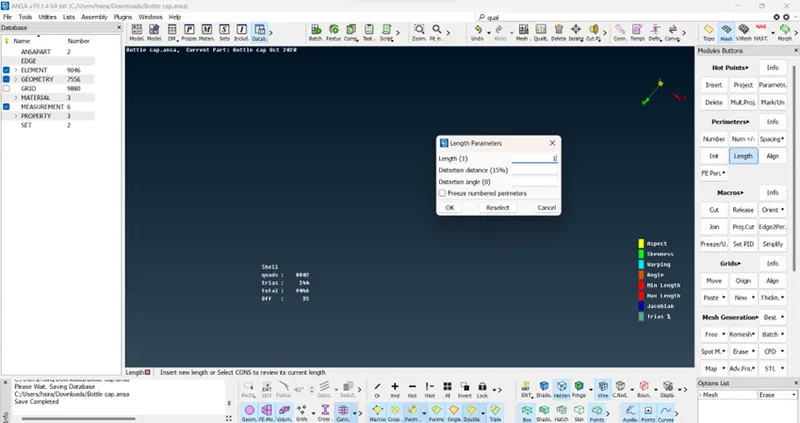
Assign the values for perimeter and macrons, Length option under perimeters is used to assign the valve.
Step 11:
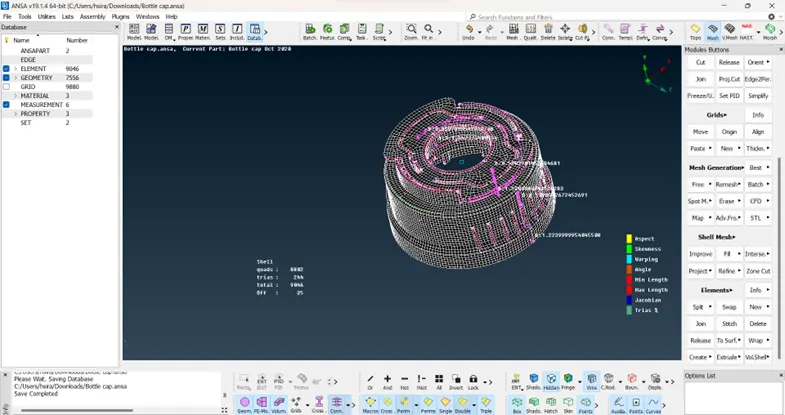
To generate the mesh flow, Best> Select, option is selected under mesh generation.
The Re-construction function is a powerful tool for the creation of a high quality surface mesh.
It examines a given mesh and performs re-meshing to correct problematic areas and optimize the overall quality of the mesh according to the mesh parameters. For Geometry Mesh (Macro Areas) all modifications are made on the underlying CAD surface.
For FE-model mesh, all modifications are made on the surface defined by the shell elements. The function may be applied to selected or to all visible meshed Macro Areas and FEM mesh according to the chosen option.
Operations :
Verify the visibility of the meshed Macro Areas or the FEM mesh to be Reconstructed.
Verify the settings defined in the 'Meshing Parameters' window.
Verify the shell mesh elements type (Mixed.., Quad.., Tria..).
Verify the status of the 2nd Ord flag, for the creation (or not) of 2nd order elements.
Press the Reconstruct button and pick the [Select] or [Visible] option.
If the [Visible] option is chosen, all visible mesh (Geometry and/or FEM mesh) is Reconstructed.
If the [Select] option is chosen, the 'Selection Window' appears. Activate the relative option buttons and input an appropriate angle value in the Feature Area to be used for the identification of the area that will be selected by one pick.
Use the left mouse-button to select the meshed Macro Areas or the FEM shell elements to be Reconstructed. If the 'Feature Area'
Learning Outcome:
- I’ve learned few new tools like
- Elements >Join – Join command is used to convert the two opposite trias connected to one node to a quad channel element.
- Elements > Swap – Swap option is used to move the trias in left/right direction.
- Elements > Split > Edge – It is used to move the trias in forward direction.
- Elements > Smooth – In order to adjust the disturbed nodes.
- Grids > Paste - It is used to move the trias in Backward direction.
- Points > On COG - This function can be used to automatically create a 3D Point as the center of gravity (geometric center - centroid)
- Transform > Rotate - This function creates new entities through the rotation of selected entities by means of a rotation axis and a rotation angle.
- Curves > Middle - This function defines new 3D Curves which lie between two selected sets of Curves or CONS.
Conclusion:
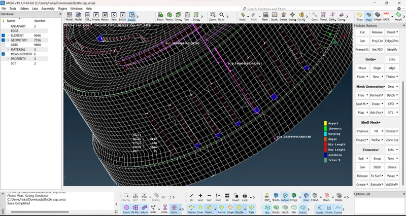
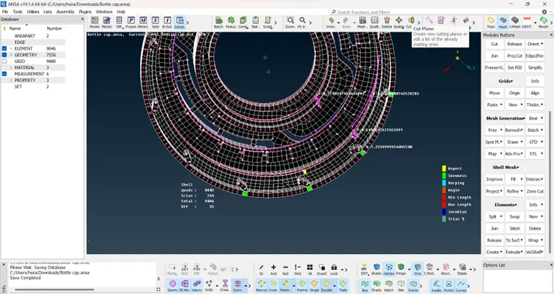
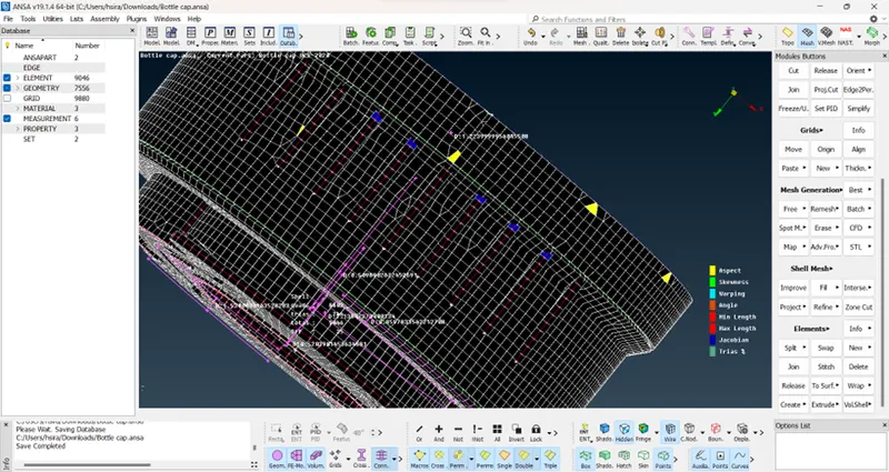
- There are 35 Failed elements near Triple CONS or at smaller regions that are bounded by two Triple CONS. Those OFF elements as it is not possible to solve.
- Elements other than those regions are passed for the above-mentioned quality criteria.