Week - 4 - 2D meshing for Plastic components
Aim -: Perform 2D meshing on plastic on component ( Bottle Cap).
Brief Intoduction About 2D Or Shell Mesh - AS we know that mesh is a network that is formed of cell/elements and
points. It can have almost any shape in any size and is used to solve PDE.
Each cell of the mesh represents an individual solution of the equation
which when combined for whole network resuts in a solution for the entire
mesh. In 2D mesh we use 2D elements(quads and trias) to capture the
entire domain of our CAD model.In shell mesh we extract midsurface from
the parent geometry and deploy the mesh network on it. After assigning
valid PID to the midsurface , the mesh network captures the entitre
volume/thickness of the CAD model.
Given CAD Model ( Bottle Cap)
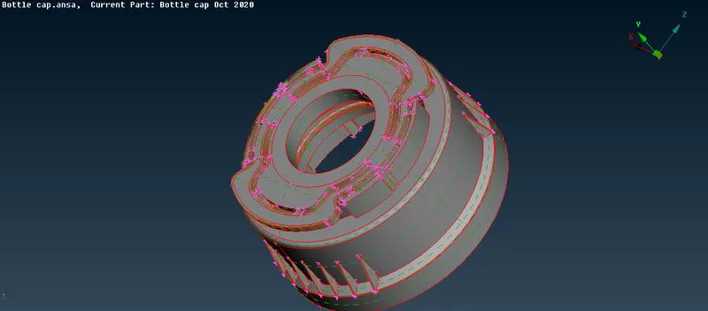
The above plastic component consist of differnt features having different thickness.
Procedure - There are various steps needed to be followed in order toget a proper mesh flow.
1. Import CAD geometry.
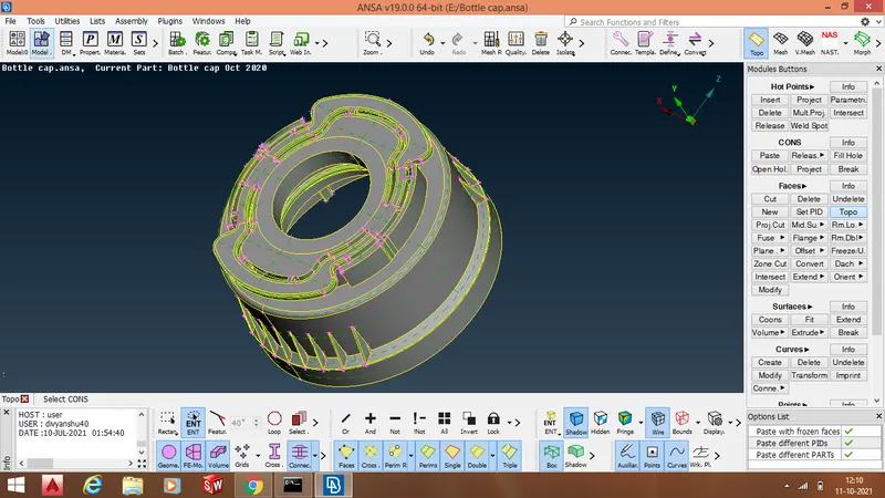
2. Perform " Faces ->TOPO" operation to connnect/stich various surfaces with each other.
3. Remove geometrical and topological errors.
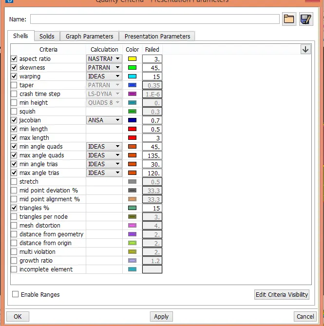
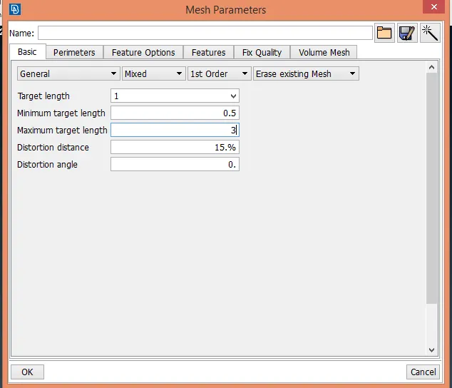
4. Insert numerical value for several elemental quality criteria and mesh parameters.
5.
6. Mesh improvement.
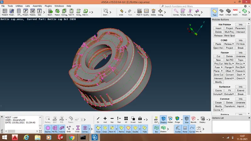
1. Import CAD geometry.
2. Perform "Faces-> TOPO"operation to stich the surfaces together
3. Removing geometrical and topological errors
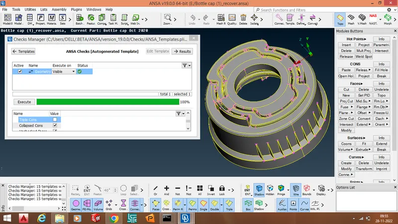
- To remove geometrical errors , we first need to find out the location and type of error in our CAD model .
- We perform "checks ->Geometry "fuction to find the location and type of geometric error in our CAD model .
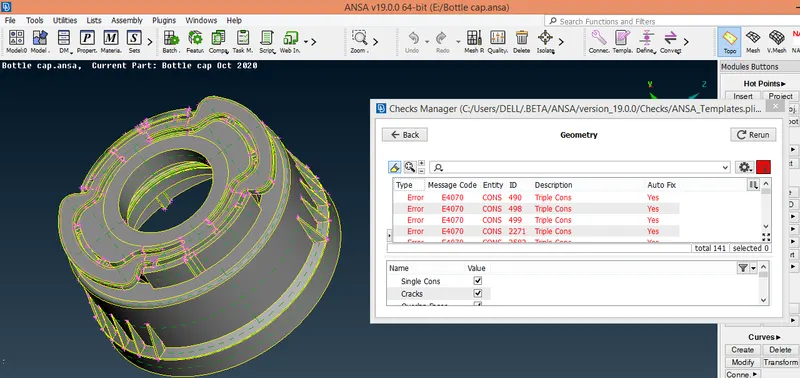
- Geometrical errors can be removed manually or through auto fix
- After removing these errors geometry is clean enough to perform meshing
4. Generation and extraction of mid surface
- The given CAD model is a plastic component having surfaces of multiple thickness
- We perform "faces -> offset" , "faces->middlle" , "faces ->extend" fuctions to perform midsurface generation and extraction.
This is a complex model so midsurface generation can be explained by images displayed below .
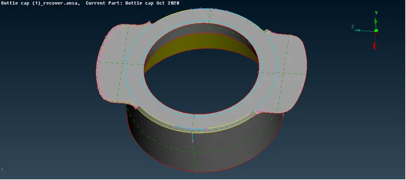
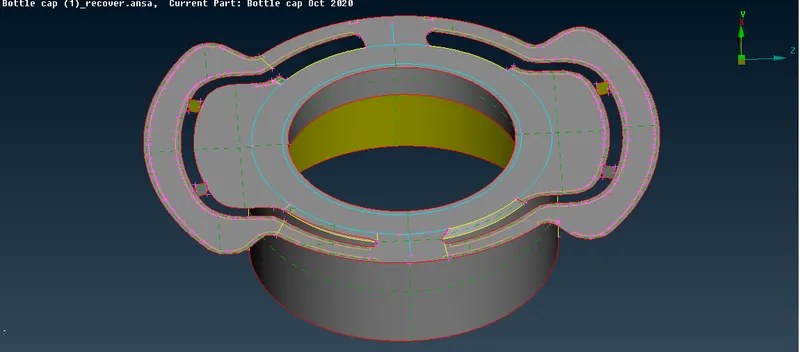
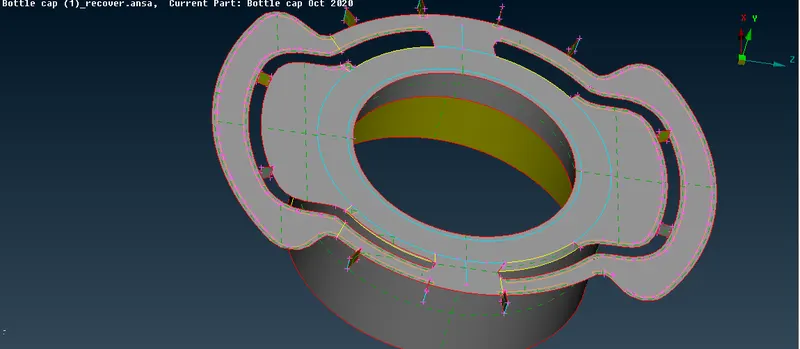
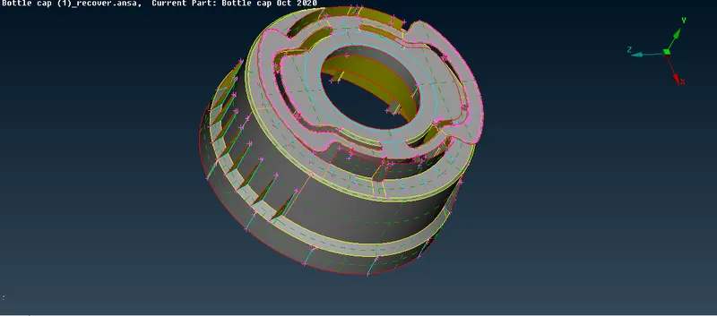
- In order to generate midsurfaces at some places we have also performed "curves ->create" , "curves->cons2curve" , "curves->project" , "curves-> middle" functions
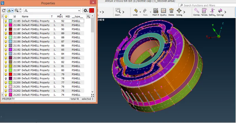
- After midsurface generation we assign seperate PID to every individual midsurface .
- Diffferent thicknesses are assigned to every midsurface on the basis o there parent surface.
5. Insert numerical value for several elemental quality criteria and mesh parameters.
6 . Deployment of mesh network
- Meshing is done in the mesh module.
- We perform "perimeter -> length" function to set the average distance between the two consecutive node points.
- we perform "mesh generation -> best" to deploy mesh network.
- quality of mesh can be improved by performing various mesh optimization functions like: "perimeter -> Num" , "perimeter-> int" , "macros-> cut" , "macros->join" , "grids->paste","shell mesh -> reconstruct" ,"shell mesh ->smooth " , "elements-> split" , " elements->swap" , "elements -> join" etc .
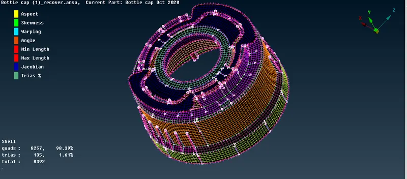
Conclusion
Entire Bottlle component have been meshed.
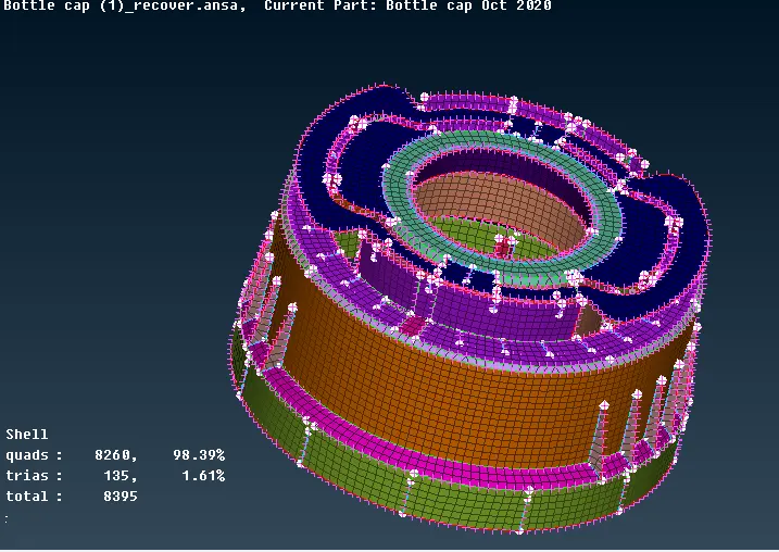
- By enabling "draw shell as solid" in quality criteria window our mesh network wil capture the entire thickness of the CAD model on the basis of thickness assinged to every individual midsurface.
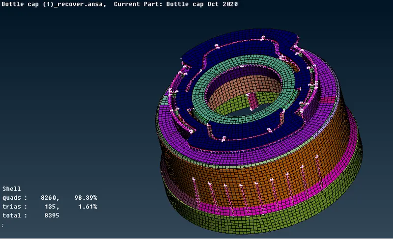
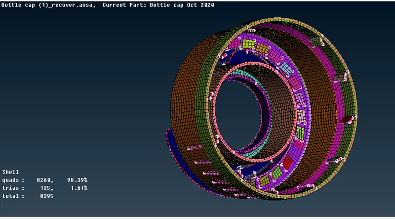
Learning Outcomes - While meshing this comonent having many regions with complex geometry , I as a CAE engineer learned to deploy mesh network with proper mesh flow by dissintegrating my entire bottle cap model into small patches and meshing one patch at a time. As a CAE engineer I have tried to keep number of tria elements as lest as possible. While handling this project we get a deeper insight of handling and mananging tria elements" by performing different operations through different commands.