Week 3 - 2D meshing for sheet metal
AIM - Perform 2D meshing on ''Car Hood" model.
Brief Intoduction About 2D Or Shell Mesh - AS we know that mesh is a network that is formed of cell/elements and
points. It can have almost any shape in any size and is used to solve PDE.
Each cell of the mesh represents an individual solution of the equation
which when combined for whole network resuts in a solution for the entire
mesh. In 2D mesh we use 2D elements(quads and trias) to capture the
entire domain of our CAD model.In shell mesh we extract midsurface from
the parent geometry and deploy the mesh network on it. After assigning
valid PID to the midsurface , the mesh network captures the entitre
volume/thickness of the CAD model.
Given CAD Model(Car Hood)
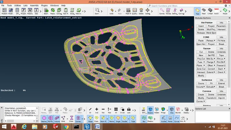
The given Car Hood model is a sheetmetal component having a uniform thickness of 0.75mm.
PROCEDURE - There are several steps that we follow to ensure a good mesh flow.
1. Import CAD model in ANSA GUI.
2. Perform " Faces -> TOPO" operation on the given CAD model.
3. Checking and eliminating geomertical and topological errors.
4. Extracting midsurface.
5. Inserting values for different quality criterias and mesh parameters.
6. Deploying mesh network on CAD model.
7. Mesh improvement.
1. Import CAD model in ANSA GUI
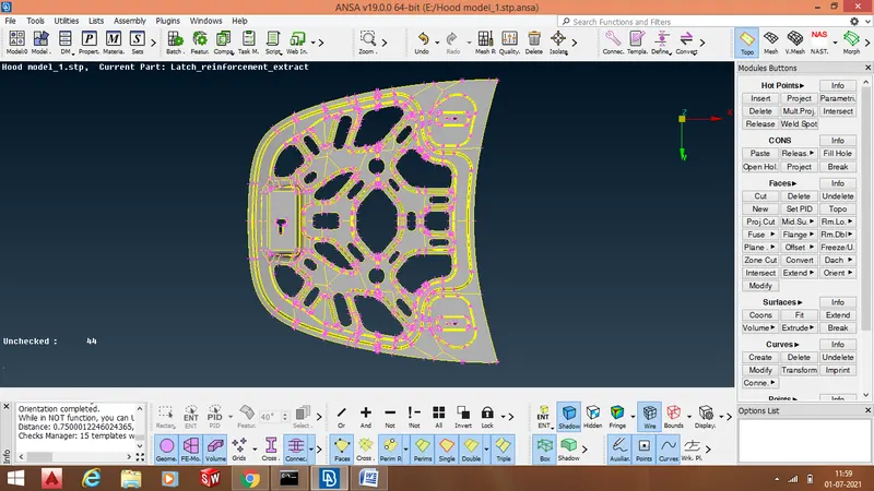
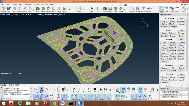
2. Perform " Faces -> TOPO" operation on the given CAD model - In ANSA every surface is bounded by" CONS and HOT POINTS" . CONS are nothing but the edges of the surface and HOT POINTS are nothing but two extremeties of a CON. We have -:
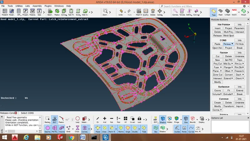
1. Single CON(Red CON) - Edge shared by only one surface.
2. Double CON(Yellow CON) - Edge shared by two surfaces.
3. Tripple CON(Cyant CON) - Edge shared by three or more than three surfaces.
- Therefore a double or tripple CONS are essential to ensure connectivity between adjacent surfaces. Initially when we import our CAD model in ANSA GUI , there might be possibility that the adjacent surfaces are not connected to each other. Which means that the CONS shared by the surfaces are RED CONS as shown below
- To ensure connectivity between the adjacent surfaces we perform " Faces -> TOPO " operation.
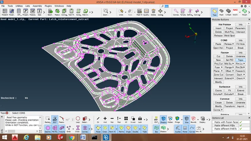
- The adjacent surfaces are now connected to each other through double CONS
3. Checking and eliminating geomertical and topological errors - To ensure proper mesh flow we remove several geometrical and topological errors. In order to check weather our CAD model is having any errors or not , we perform " checks -> Geometry" operation. There are total 169 errors in CAD geometry.
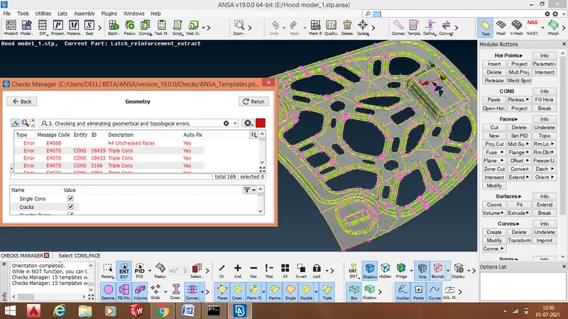
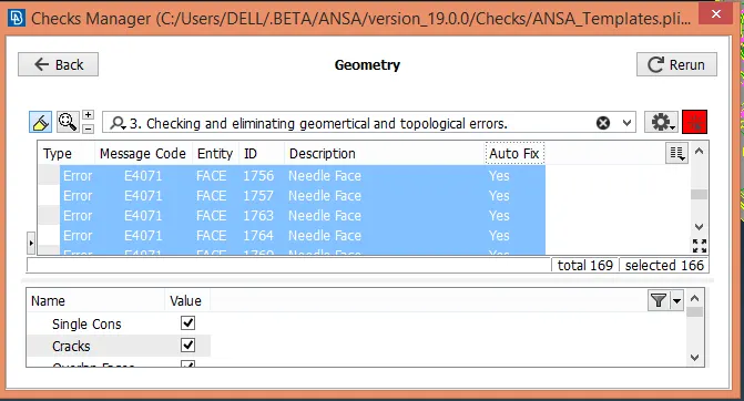
- Most of the errors can be autofixed by ANSA.
- After autofix we are left with 29 errors , these we have to remove manually.
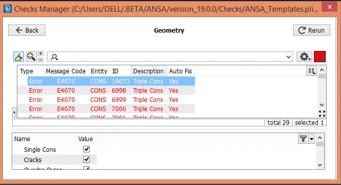
- Errors to be removed manually
1. Tripple CONS formed due to very less gap between top and bottom surfaces.
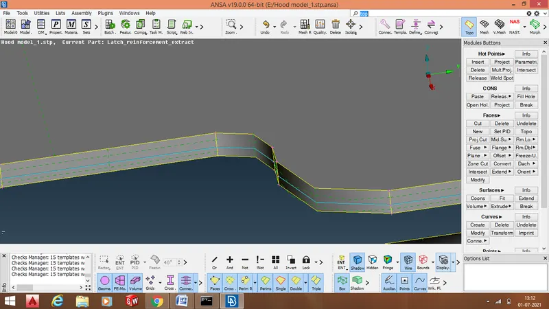
- This error can be removed by releasing the triple CONS and performing Topo operation.
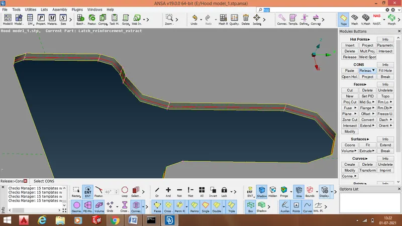
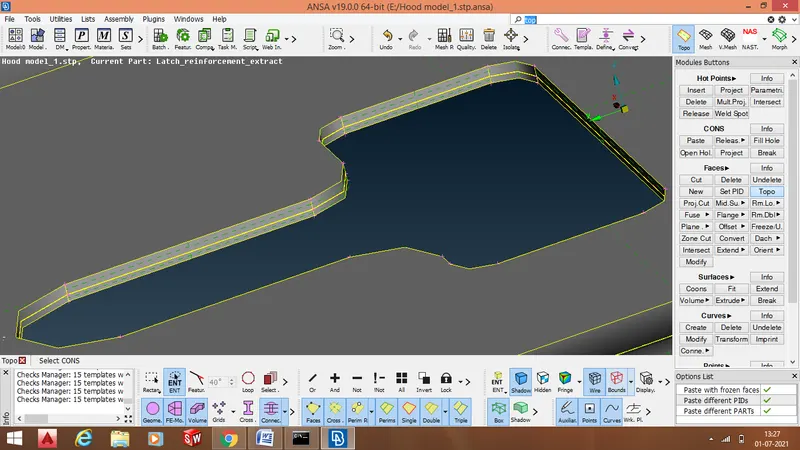
2. Removing triple CONS from other region having hole or opening.
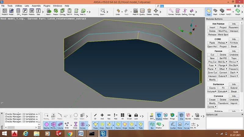
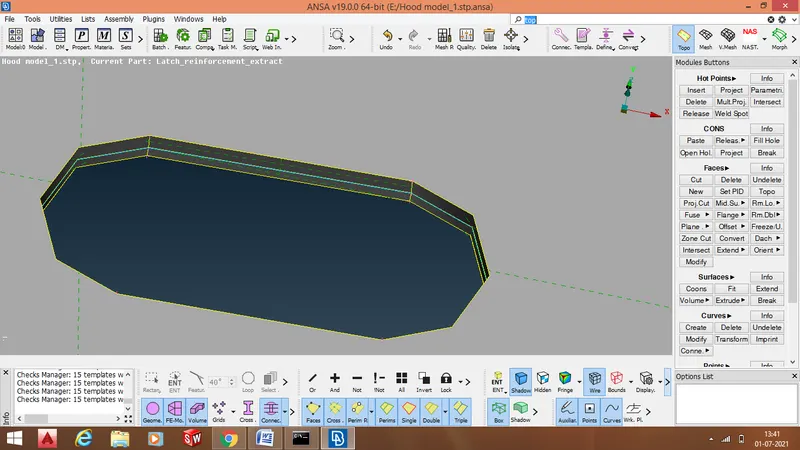
Such errors are arising because the surfaces are connected to each other in an improper way. To solve such errros we need to remove connectivity between the surfaces by performing " CONS -> Release" operation. When the connectivity is removed we stitch adjacent surfaces together properly by performing "Faces -> TOPO" operation.
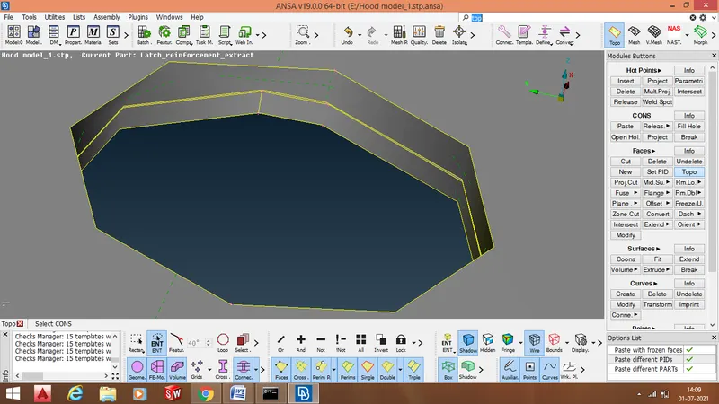
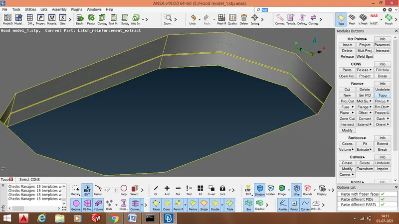
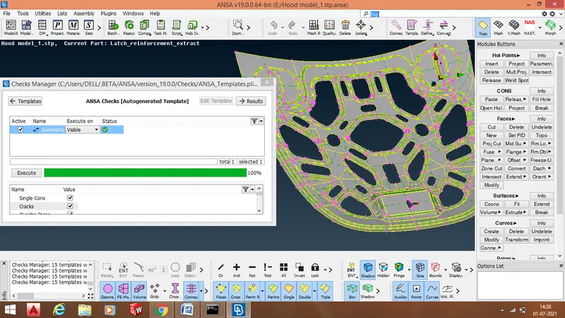
- After removing all geometrical and topological errors ,the "Geometry" template shows that the CAD model is completely free from all geometrical and topological errors by displaying 100% clean geometry.
4. Extracting midsurface. - This is an important step in ANSA or in CAE which has to be followed. this contributes to most of the preprocessing time. Skin/mid surface is a neutral face which is generate from the parent CAD geometry. In midsurface extraction we breakdown our 3D CAD model into 2D model.THere are several commands used to extract midsurface, the most common is " Faces -> Offset" command. We select various surfaces through "feature area" selection, it allows to select various surfaces on one side of the "Hood" model at once. The feature angle used is 40 degrees . In this case offset value mentioned is -0.375, - or + signifies direction in which offset face needs to be taken.
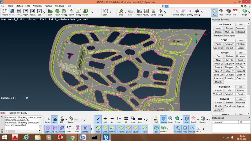
- After extracting midsurface , we assign a seperate PID to the midsurface.To assign a seperate we perform "Faces -> SET PID " operation . while assigning a seperate PID to the midsurface we also assign thickness to the midsurface equivalent to the parent geometry.
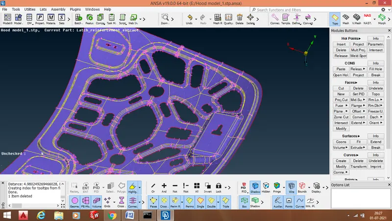
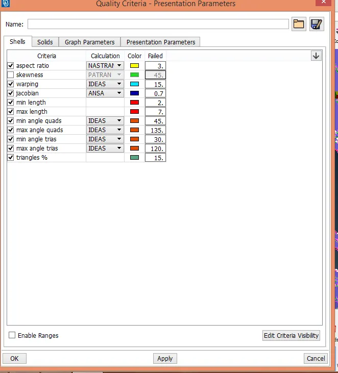
5. Inserting values for different quality criterias and mesh parameters. - There are certain criterias on which the quality of mesh elements depends. To ensure a proper mesh flow it is important that the mesh elements should satisfy the numerical values or numerical ranges of these quality criterias. Mesh parameters are nothing but the parameters that decide the type of mesh deployed on the surface. While assigning values of several qualty criterias we also provide element length . There are generally three types of elements lengths -: average length , maximum length , and minimum length. Mesh parameters also include type of elements like quads , trias etc.
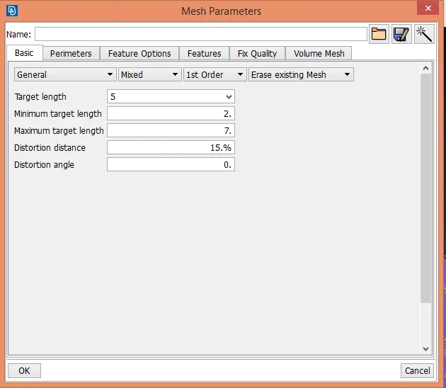
5. Deploying mesh network on CAD model. - Before deploying mesh network on the midsurface we assign average element length to the mesh elements by performing " Perimeters -> Length"operation.we assign average length of 5mm.
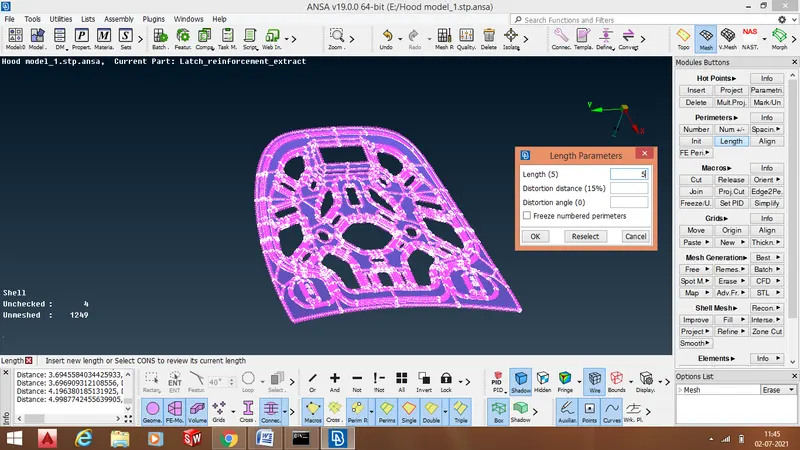
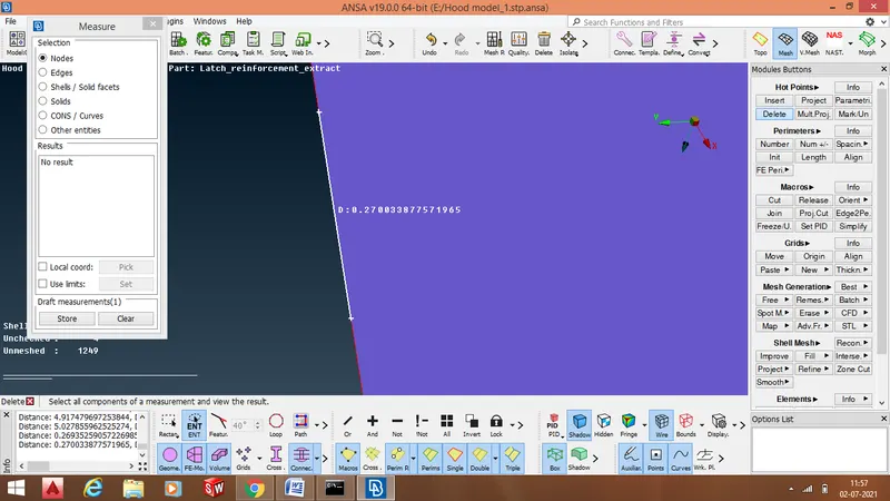
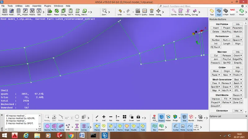
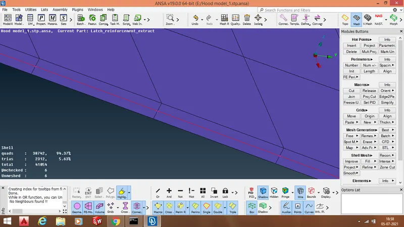
- After assigning average mesh element length we check our CAD model area by area to se weather the length criteria is satisfied at every macro or not. In case any macro does not satisfy the length critera , we solve this issue by performing " Perimeters -> Length" and " Perimeters - > Init" operation on the CONS of the concerning macros. In the below example we acn see that the distance between the two consecutive node points does not satisfy the length criteria.
- As we can clearly se that the given Hood model is having symmetric geometry, so we will be deploying mesh network on one half of the two symmetric portions, and then by performing symmetry operation we will copy the geometry along with the mesh network on adjacent side of the already meshed geometry.
- Therefore initially we will perform meshing on the geometry given below.
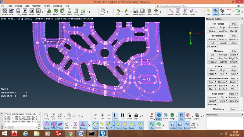
There are certain protocols or rules that we follow while deploying a mesh network on the midsurface :
- We disintegrate our CAD geometry into small patches, and mesh each patch/region at a time.
- We avoid back to back connected tia elements.
- We avoid tria near the edge as much as possible.
- We try to increase the distance between opposite facing trias.
- To ensure proper mesh flow mesh elements should ne proprtly alligned with respect to each other
- We try to keep number of tria elements as least as possible.
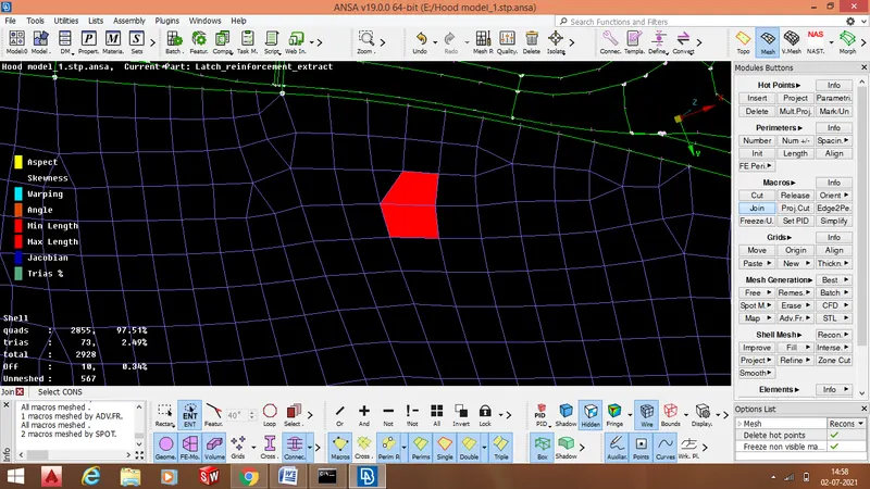
While meshing , we come across several regions in our CAD model that are so small that they will not satisfy the element length criteria, thesecregions can be eliminated or merged with the adjacent large region. This process is called defeaturing. Defeaturing can be done in TOPO module by using " Faces -> Cut" operation and defeaturing can also be done in Mesh module by using " Macros -> join" operation.
The region to be defeatured is a triangular in shape as shown below.
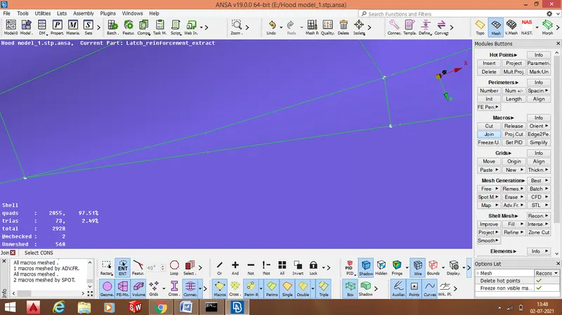
The triangular region now gets eliminated or merged with the adjacent region through the process of defeaturing.
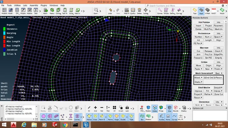
- We can see in the above images that we have dissintegrated our entire CAD geometry into small patches.
- These patches are meshed one by one . This technique helps us to maximize the number of quad elements
and minimize the number of tria elements.It also helps us to improve the quality of mesh flow.
To know weather our mesh elements are satisfying the quality criteria or not we view our CAD model in the " Hidden" drawing styles mode. The mesh elements failing for our quality criteria gets highlighted with different colours as shown below.
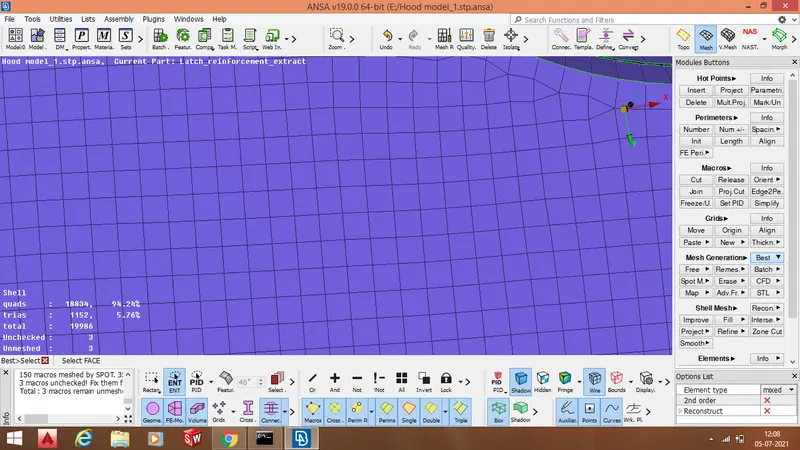
- ANSA provide various algorithms to deploy good quality mesh like " Best Mesh , Free Mesh , Batch Mesh , Spot Mesh , Mixed Mesh" etc.
- We generally use " Best Mesh " algorithm , because it deploy optimum quality elements on the basis of the quality criteria value.
- To ensure good mesh quality we divide the entire geometry in patches and deploy mesh network on every single patch one by one.
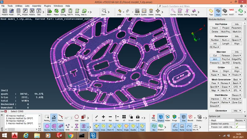
- After meshing we join different patches together by performing " Macros -> join " operation.
- There are various commands that we use to improve the shell elements quality and mesh flow like "Shell Mesh -> smooth" , " Shell Mesh -> reconsrtuct" .
- " Perimeters -> Num" is also use to manage tria elements.
The mesh flow is good when all the shell elements are properly alligned with respect to each other as shown below.
- The car hood model has a symmetric geometry , so we meshed one half of the the geometry as shown below.
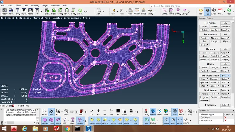
- After meshing one half of the hood model we will perform symmetry operation too deploy mesh on the other half .
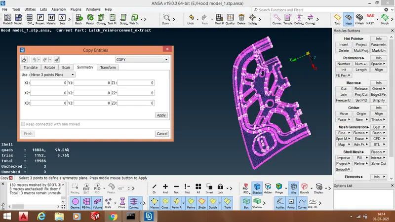
After performing symmetry operation , the mesh network is deployed on the entire CAD geometry
- After meshing the entire midsrface , we will capture the entire thickness of our CAD model through mesh network by activating " Draw Shell as Solid " command. we can see in the below image that mesh has captured the thickness of our CAD model.
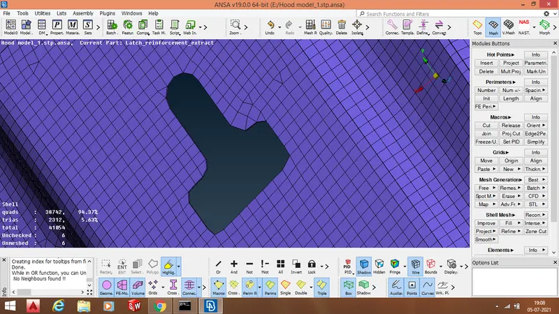
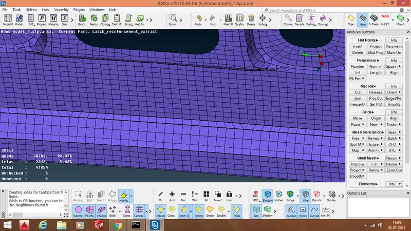
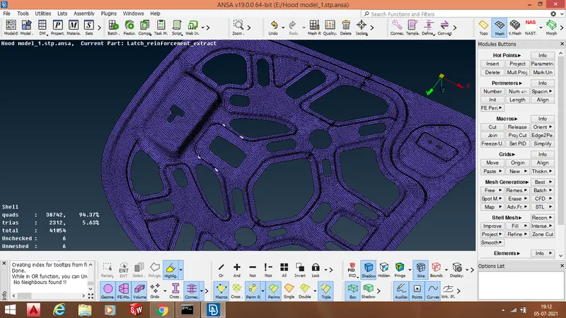
Conclusion - The entre Hood model has been meshed with the mesh flow of optimum quality , the shell elements satisfy the given quality criteria. In the below images there is show different meshed regions of the hood model.
Learning Outcomes - While meshing this comonent having many regions with complex geometry , I as a CAE engineer learned to deploy mesh network with proper mesh flow by dissintegrating my entire Hood model into small patches and meshing one patch at a time. As a CAE engineer I have tried to keep number of tria elements as lest as possible. While handling this project we get a deeper insight of " handling and mananging tria elements" by performing different operations through different commands.