Week - 4 - 2D meshing for Plastic components
Question:
For the given Plastic Bottle Cap model, check for the geometrical errors and take the mid surface by suitable mid surfacing techniques. PID and Thickness assignment has to be done for all the mid surfaces. Mesh the same with the given element Quality criteria. (Refer to the table below for the Quality criteria)
|
S.No |
Quality Criteria |
Value |
|
1 |
Target/Average length |
1 |
|
2 |
Minimum Length |
0.5 |
|
3 |
Maximum Length |
3 |
|
4 |
Aspect |
3 |
|
5 |
Warpage |
15 |
|
6 |
Skewness |
45 |
|
7 |
Jacobian |
0.7 |
|
8 |
Minimum Quad Angle |
45 |
|
9 |
Maximum Quad Angle |
135 |
|
10 |
Minimum Tria Angle |
30 |
|
11 |
Maximum Tria Angle |
120 |
|
10 |
Tria Percentage |
15 |
Solution:
Now we will look at meshing of Plastic component (Bottle cap).
Quality Criteria:
Quality criteria for the meshing of all the components are given as follows:
- Target Element Length: 1 Units.
| Sr. No. | Quality Criteria | Value |
| 1 | Target/Average length | 1 |
| 2 | Minimum length | 0.5 |
| 3 | Maximum length | 3 |
| 4 | Aspect ratio | 3 |
| 5 | Warpage | 15 |
| 6 | Skewness | 45 |
| 7 | Jacobian | 0.7 |
| 8 | Miniimum Quad Angle | 45 |
| 9 | Maximum Quad Angle | 135 |
| 10 | Minimum Tria Angle | 30 |
| 11 | Maximum Tria Angle | 120 |
| 12 | Tria Percentage | 15 |
Manual mid surface of the Plastic component:
Let's look at how to take mid surface of the plastic component so further we can make a shell mesh for the component.
Here we tried taking auto midsuface but ANSA did'nt helped us with it, so we will have to take mid surface for this component manually.
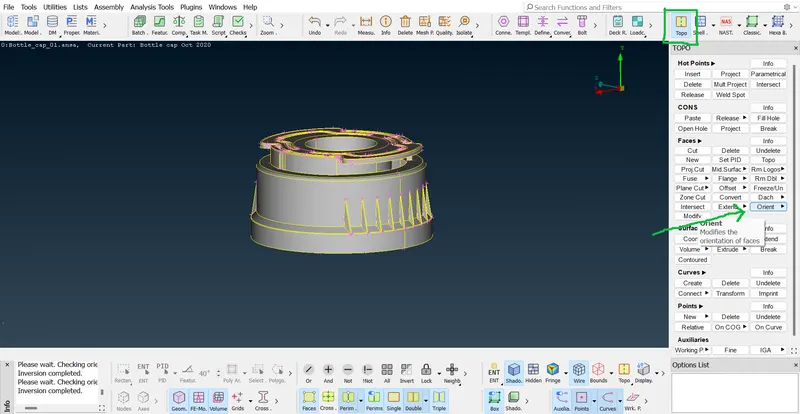
Fig1.1: Performing the 'Orientation' operation on the Bottle cap.
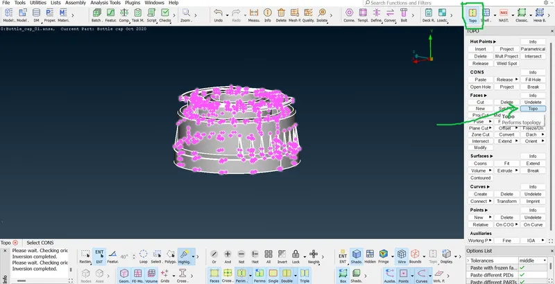
Fig1.2: Performing the 'Topo' operation on the Bottle cap.
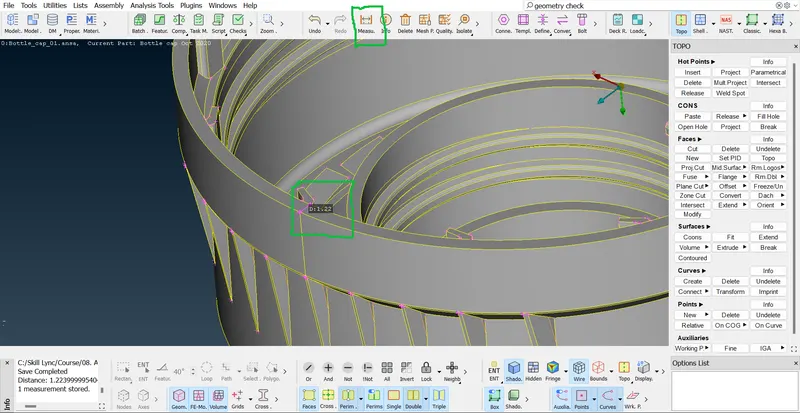
Fig1.3: Measuring the thickness of the wall and features of the component.
Since we need to create the mid surface of the component manually, we must know the thickness of the features of the component. Therefore taking the measurements of the features using the 'Measure' command.
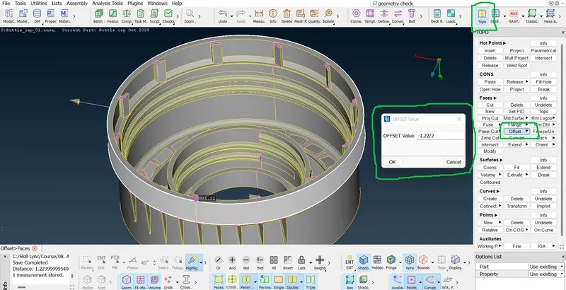
Fig1.4: Executing the offset command for the selected surface.
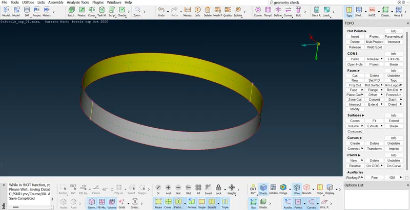
Fig1.5: Extracted mid surface of the Base of the outer shell.
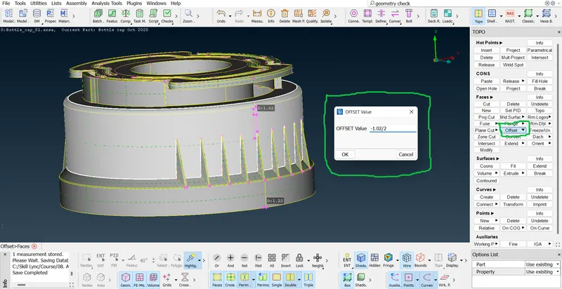
Fig1.6: Executing the 'Offset' operation on the middle surfaces of the outer shell.
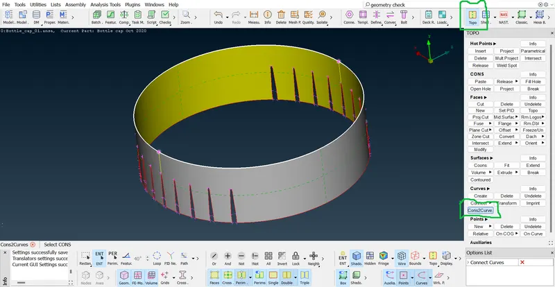
Fig1.7: Extracted mid surface of the middle surfaces of the outer shell.
Here we need a smooth surface without any feature lines and points on it, to obtain the optimized quality of the mesh. There we must execute some extra operations to achieve it.
Performing the 'Cons2curve' operation to obtain the curves of the surface edges.
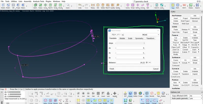
Fig1.8: Executing the 'Tranform' operation on the obtained curve.
The obtained curved is now copied and translated at the distace according to the dimension of the component.
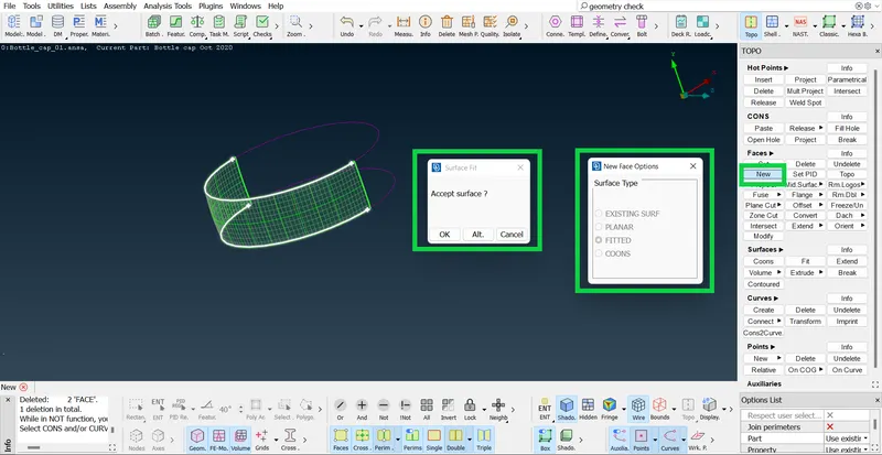
Fig1.9: Executing the 'New surface options' to create new smooth mid surfaces.
New surfaces (smooth mid surfaces) are obtained using the extracted curves.
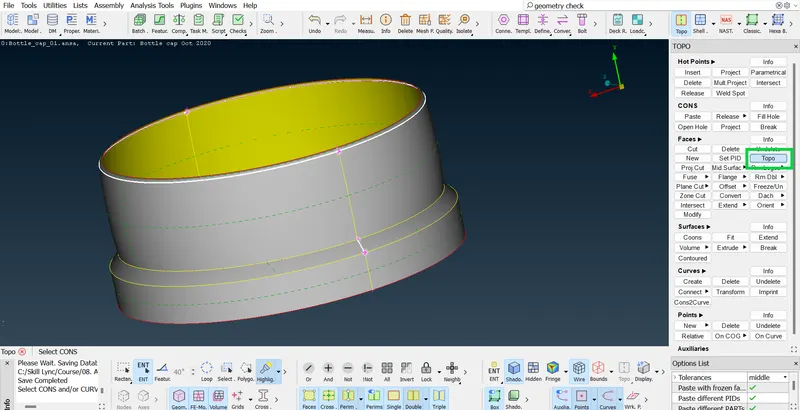
Fig1.10: Executing the 'Topo' operation to join the newly created surfaces.
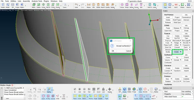
Fig1.11: Executing the 'Middle' operation to extract the mid surface of features like ribs.
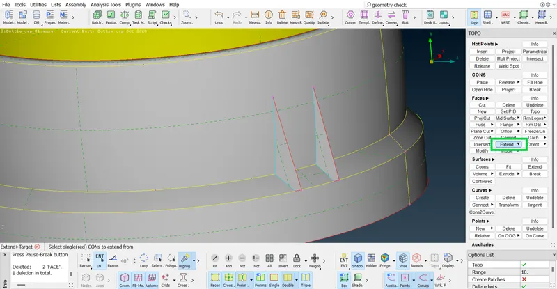
Fig1.12: Extracted mid surfaces of the ribs followed by the 'Extend' operation.
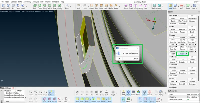
Fig1.13: Executing the 'Middle' operation to extract the mid surface of features.
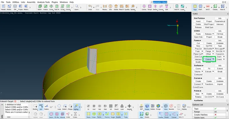
Fig1.14: Extracted mid surfaces of the ribs followed by the 'Extend' operation.
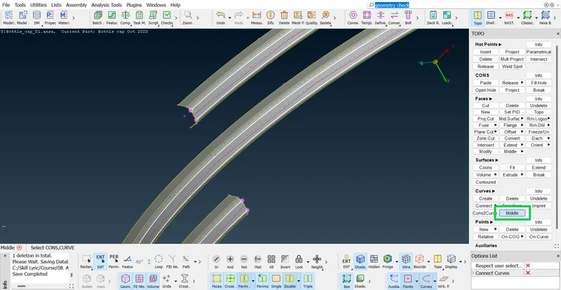
Fig1.15: Executing the 'Cons2curve' operation on the inner threads of the outer shell.
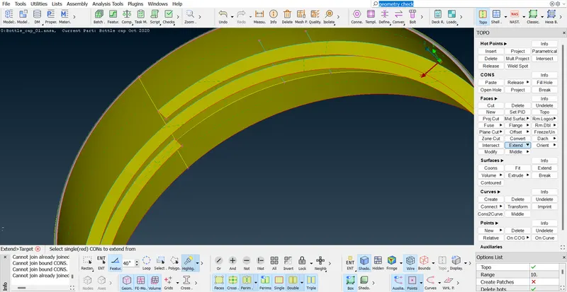
Fig1.16: Creating the new mid surfaces for inner threads of outer shell using the previously extracted curves.
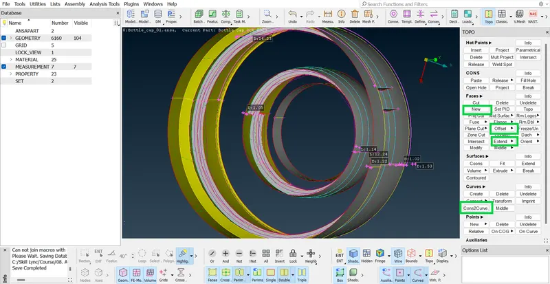
Fig1.17: Creating the new mid surfaces for the inner shell and inner shell threads.
Same procedure, commands and operations are executed to obtain the mid surfaces for the inner shell and inner shell threads.
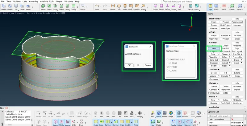
Fig1.18: Creating the mid surface for the top of the bottle cap.
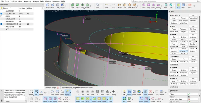
Fig1.19: Creating the mid surfaces for the top side walls of the bottle cap.
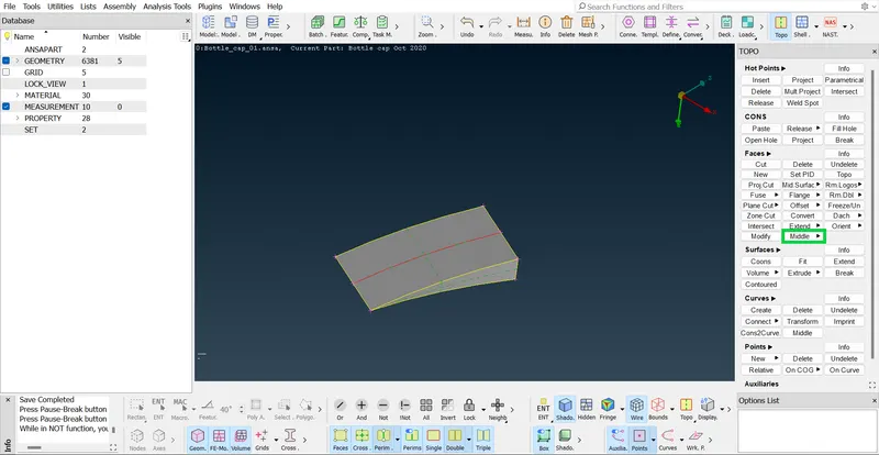
Fig1.20: The mid surface is obtained by using the 'Middle' command for the feature.
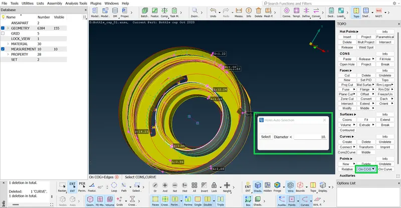
Fig1.21: The centre is obtained by executing the 'On COG' command on the specified curves.
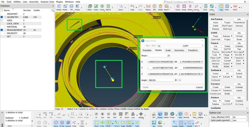
Fig1.22: Executing the 'Rotate' operation for obtaining the required mid surfaces of the feature around the centre line.
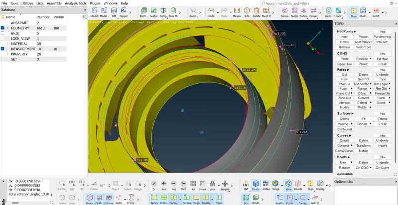
Fig1.23: Mid surfaces of the feature around the centre line.
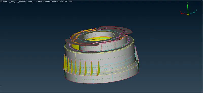
Fig1.24: Complete manually obtained mid surfaces of the component.
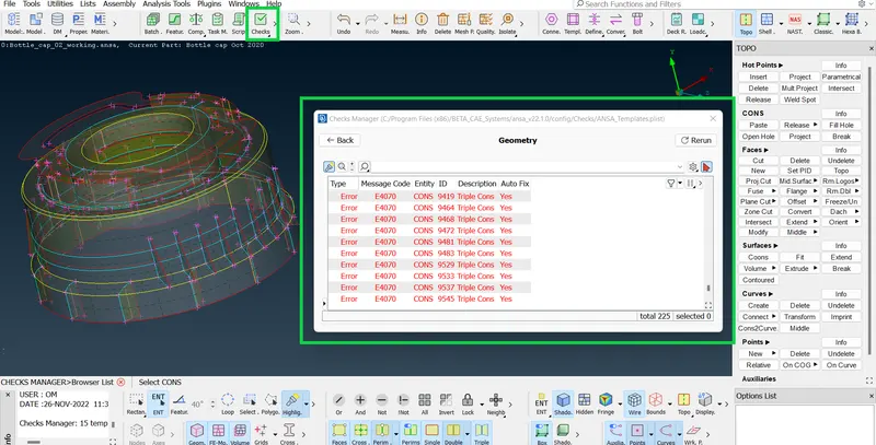
Fig1.25: Checking the manually obtained mid surface for the 'Geometry' checks.
Here the warnings shown for triple cons are not considered since the surface consists of the features for which the triple cons are necessary.
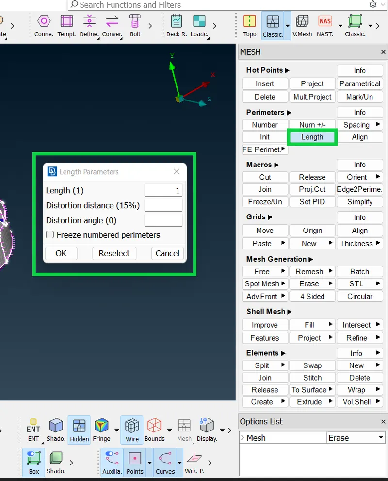
Fig1.26: Executing the 'Length (perimeters, Micros) command before meshing.
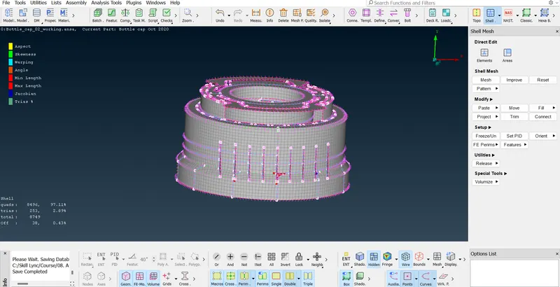
Fig1.27: Meshing the surfaces of the component one by one.
Mesh the surfaces of the component one by one.
Reconstruct the mesh if necessary and smooth the reconstructed elements.
Try spliting trias and to avoid trias facing each other and touching each other.
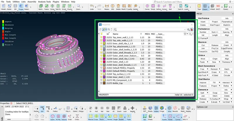
Fig1.28: Assign the specified thickness to the given surfaces.
Learning outcomes:
- We learnt and practiced, How to create mid surface for automotive plastic components.
- To obtain the good mesh flow for automotive plastic components with minimum number of elements failing for quality.
- To assign the thickness and other properties to the extracted mid surface of the component.
Conclusion:
We studied and practiced the meshing of plastic components with proper mesh flow, as per the quality requirements of the automotive industries.