Week - 4 - 2D meshing for Plastic components
2D Meshing for Plastic component
Aim:
To convert the given plastic bottle cap from CAD to CAE model for FE analysis using ANSA pre-processor.
Procedure:
- Import the CAD geometry into ANSA pre-processor
- Perform geometry clean up and study the CAD
- Identifying critical areas
- Extract mid surface for various regions
- Perform 2D meshing on extracted mid surfaces
- Maintain element quality as per prescribed guidelines
- Create various property cards and assign different thicknesses
Import the CAD geometry into ANSA pre-processor
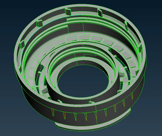
- The given CAD geometry in the native STP format is imported into ANSA by just dragging it into ANSA Workspace. The CAD geometry is shown below.
Perform geometry clean up and study the CAD
- Geometry clean-up can be performed by clicking on the Geometry menu from the check’s manager
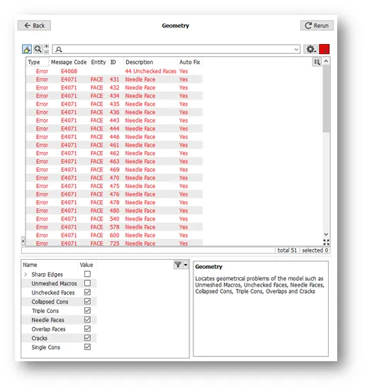
- The checks manager will appear and clicking on the execute button will identify the topological errors in the geometry. Right clicking on the error will fix it. If ANSA is unable to fix the issue, then it has to be fixed manually
- The Geometry checks manager is shown below. The items highlighted in red are the topological errors.
- Fortunately, in this geometry no topological errors were present.
Identifying critical areas
It is challenging to obtain the midsurface for certain topological features show below and extend them to the midsurface to the external and internal walls
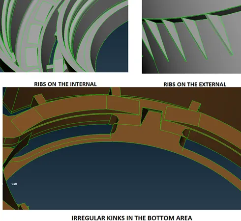
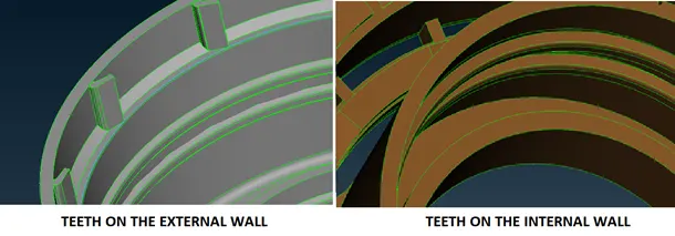
Extract Mid Surface for Inner and Outer Panels
- The mid can be done easily using the Middle > option for the inner and outer walls. The user must ensure that proper selection of red, green and blue areas are done
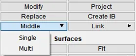
- If this option fails, it is easier to offset the face using the Faces > Offset option.
- For the critical areas advanced methodologies must be used. Creation of curves in between the CONS of the areas and projecting them on to the surface is one effective way of obtaining mid surface.
- For example, for the external ribs the middle curve method will work perfectly.
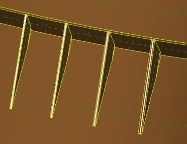
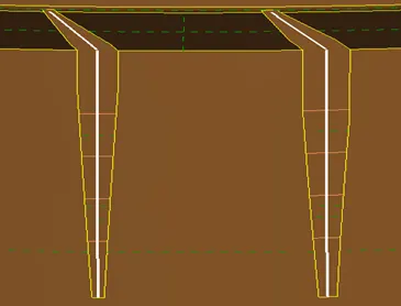
- Then hiding the ribs will expose the inner area of the rib using which we can create another set of curve and finally faces can be created by joining the curves as shown below
- In some areas like the ribs on the internal it is sufficient to obtain the middle surface for one rib and use the rotate option to rotate the face multiple times
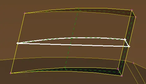
- The finally extracted and fixed midsurface will look like the one shown below. It may still have some topological issues. It is diligent to ignore them for the time being and start meshing and correct the FE if needed.
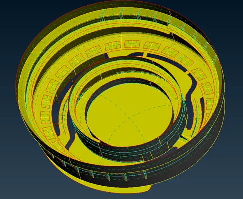
Perform 2D meshing on extracted mid surfaces
- 2D Meshing is a fairly easier process. Using the BEST option to generate a mesh yields the best results. Then reconstructing and smoothening the mesh givers proper flow.
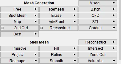
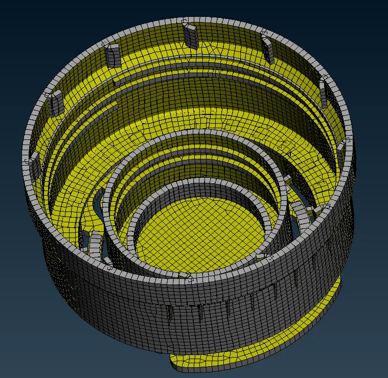
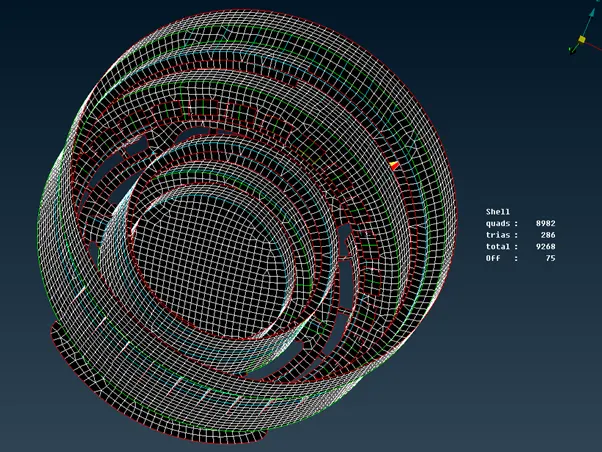
- The final mesh looks like the one shown below.
Maintain element quality as per prescribed guidelines
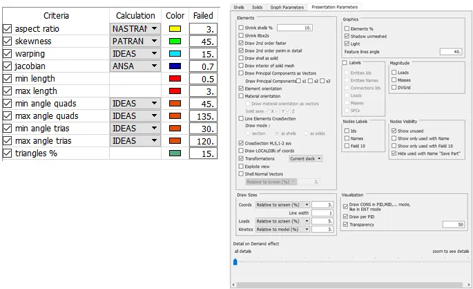
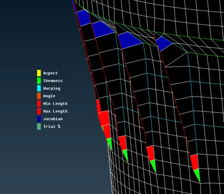
- Of course, there will some failed elements in the external ribs, it is not possible to correct them in a short span of time. So, avoiding them for the time being.
Learning outcomes
- Increased dexterity with respect to using the tool
- Confidence to extract midsurface and mesh plastic components
- Mastered Topology module
Result
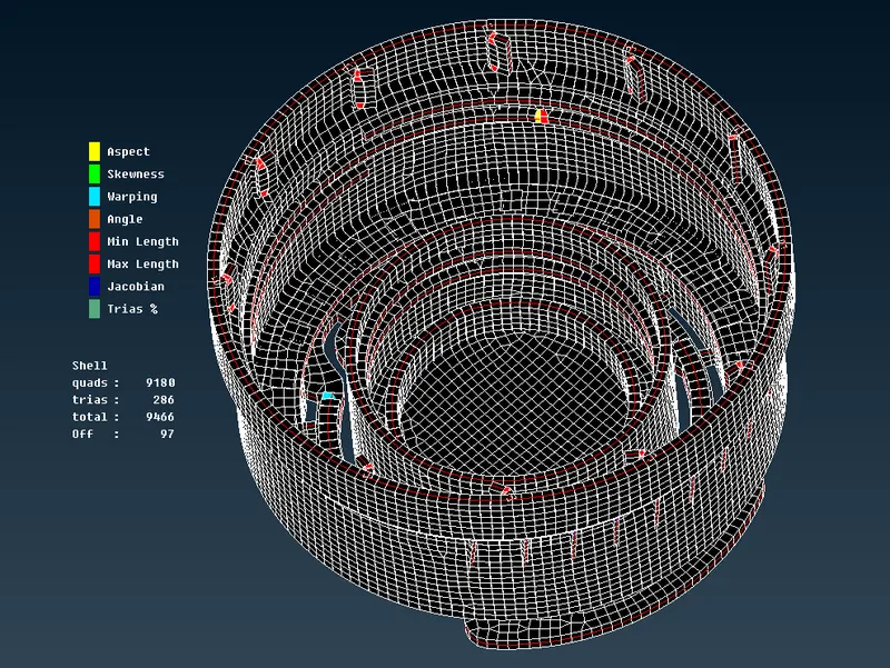
The final meshed component with 1 % OFF elements and approximately 3 %triangular. The obtained FE is at least 90 percent in agreement with the CAD upon visual inspection