Week - 4 - 2D meshing for Plastic components
#11. / 2D Meshing for Plastic Components.
AIM: 2D meshing for Plastic components.
OBJECTIVE: To check for the geometric errors, extract the mid surface with suitable technique and perform meshing on the plastic bottle cap with mentioned quality criteria.
PROCEDURE:
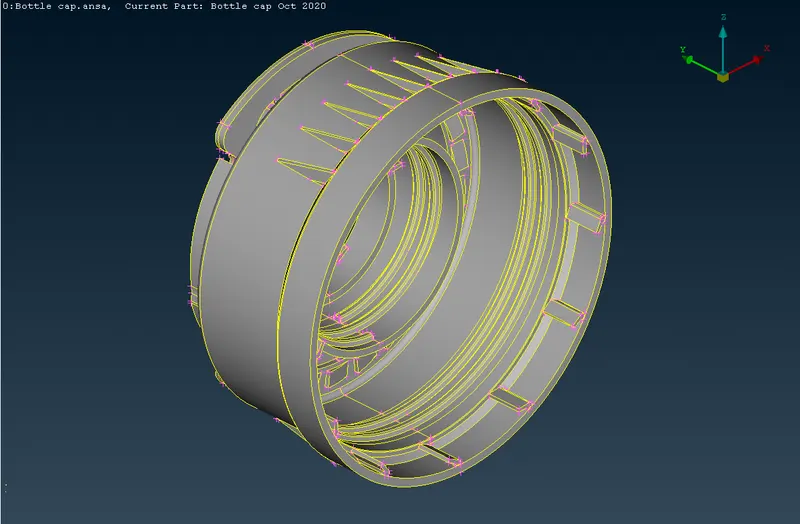
The following image shows the isometric view of the plastic bottle cap.
- In order to have a refined look of the component, nodal distance is required to be shortened.
- For the refinement go to MESH > Perimeters > Length
- Click on Perimeters option in the selection window and select the whole component with box selection and confirm the selection
- In the length, parameters set the length to 1 mm
- The same steps are followed with Macros selection option
GEOMETRY CHECK:
- Perform the geometric checks to verify if there are any geometric issues such as triple cons, needle faces, distortion etc
- Before performing the checks, the geometric errors are attempted to fix beforehand using ‘topo’ function. Go to TOPO > Faces > Topo and select the whole component and confirm
- Go to Menu Bar > Tools > Checks > Geometry and select all the errors that need to be eliminated and click on execute.
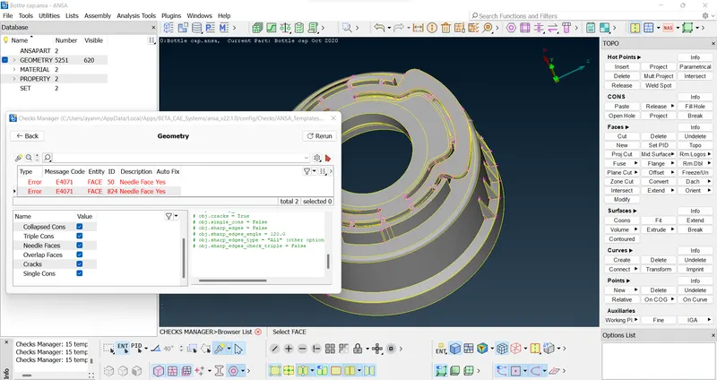
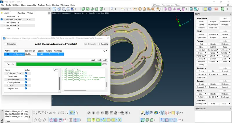
The above-shown errors are encountered. This is rectified using the auto-fix function by selecting the errors, right-clicking and selecting the Fix option. This clears all the triple cons issues.
MIDSURFACE EXTRACTION:
Since the model has complicated geometry, the auto mid generator fails. Hence manual extraction of mid-surface is preferred.
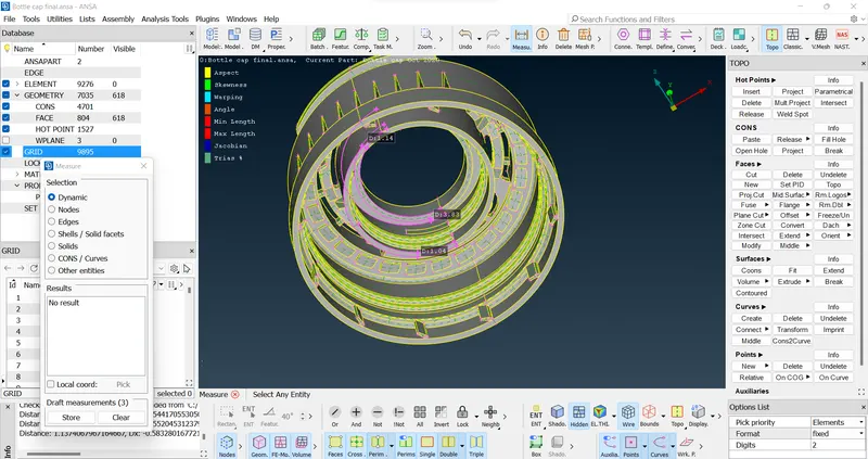
- The inner side of the cap has 2 concentric cylindrical structures. For these, the mid surface can be generated using TOPO > Faces > Offset function
- The outer and inner structures have thicknesses of 1.04 mm and 1.14 mm
- The outer surface of the outer cylinder is selected and on confirmation, offset value window appears. It is set to negative half the thickness value since the grey entity has negative orientation.
- For the inner structure, inner surface is selected and mid surface is extracted.
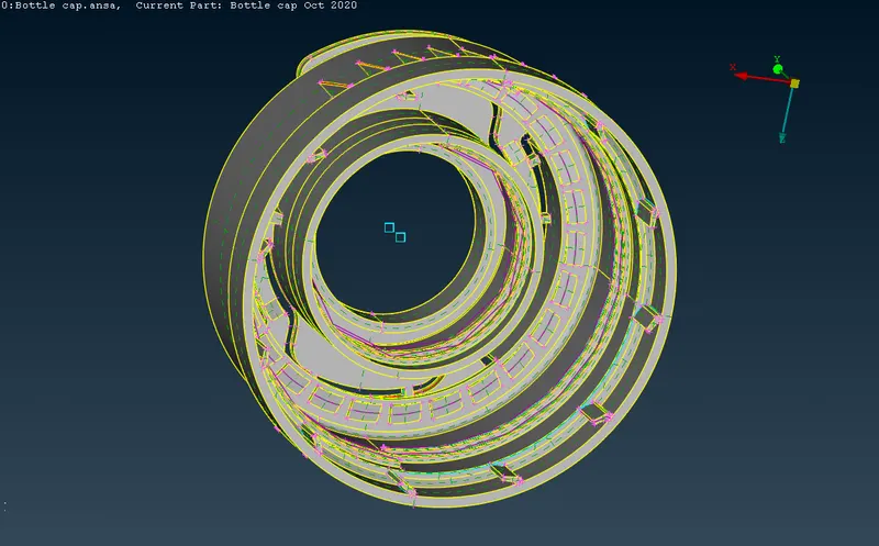
- The image shows the threads on the inner side of the bottle cap. These structures need to be captured in the mid surface.
- The curves are generated in the top-mid portion of the threads using TOPO > Curves > Middle
- Double con on one side is selected first, after middle-mouse click confirmation the second double con is selected.
- The mid surface is extracted for the teeth by creating a curve. The larger lengths of the rectangular face of the teeth are chosen and a curve is created in the middle using TOPO > Curves > Middle function. This created a purple line.
- The double con that represents the converged end of the teeth is projected on the mid surface of the bottom plate using TOPO > Cons > Project then selecting the con and subsequently selecting the bottom surface
- Both: the curve and the projected con is selected to create a new face through COONS function in TOPO > Faces > New.
- Since the teeth feature are in rotational symmetry, transform function is used to copy the mid surface
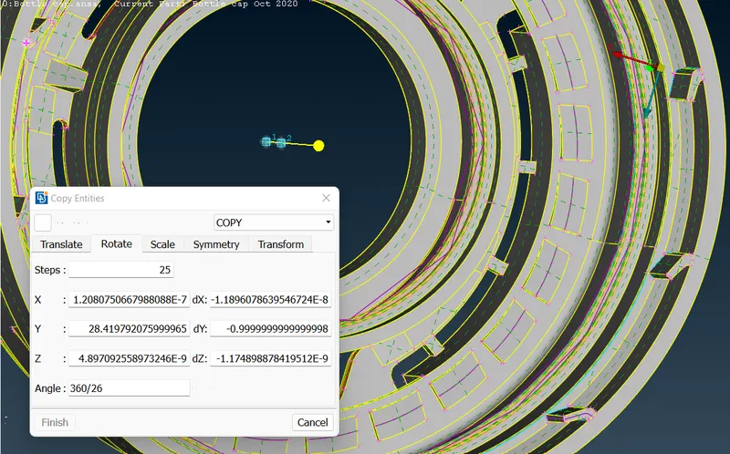
The axis of rotation is required for copying the entity in rotational format. Hence 2 COGs (Centre of gravity) are created using TOPO > Points > On COG (Edges)
[ for COG we need to selected two different dimensional circle for two diff. dimensional COG]
Two circular edges are selected at different heights and confirmed.
Then the feature entity is copied using Menu Bar > Utilities > Transform ( Rotate ) function. First COG is selected for X and second COG is selected for dX. This creates the axis of rotation. Manually created one is fed as Steps since 25 copies are required and Angle is fed with the angle between two feature entities from COG : 360/26 degrees.
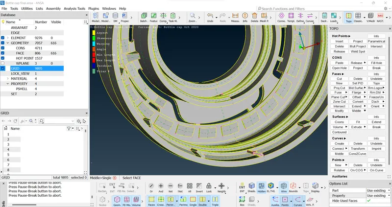
- The image shows the ribs present on the inner side that are of variable thickness. The ribs are identical.
- Initially, mid surface is extracted with TOPO > Faces > Middle (Multi) option
- The red, green and blue faces are selected that are the top, bottom and middle thickness surfaces respectively.
Since the mid surface is not proper, alternative method is opt
The curves are created on either side of ribs using TOPO > Curves > Middle function. The edges of the top skin of rib are selected first and bottom face edges are selected for second group of cons and confirmed.
The two curves are used to create new face using TOPO > Faces > New > Coons. This creates the following mid surface.
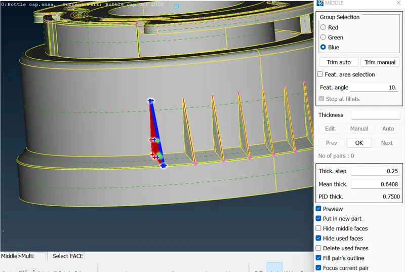
These are the ribs on the outer periphery of the bottle cap.
- The mid surface for this rib is created using TOPO > Faces > Middle (Multi)
- The red and green faces are selected on either side of the rib and the blue face is selected to represent the rib thickness
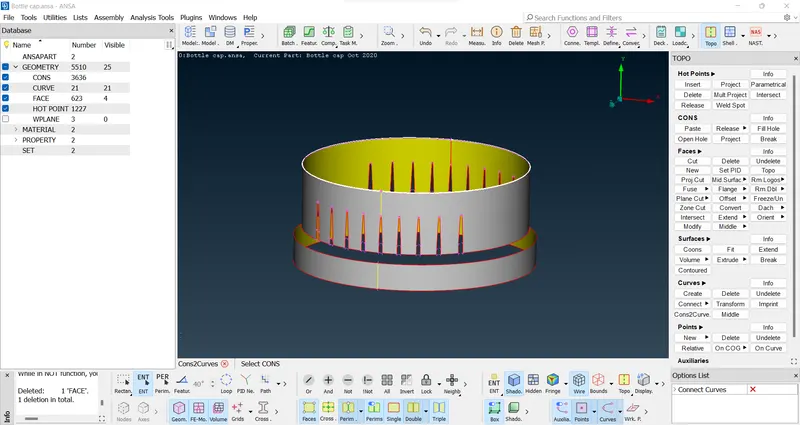
- The outer cover of the cap is shown. The mid surface for this part is created using TOPO > Faces > Offset function. Since the cover thickness is 1.22 mm, -0.61 mm is entered as the offset value.
- This shows the generated mid surface for outer cover. Then using Cons to curve for upper circle section, then delete that face, now Transform > copy > select the curve in ‘-Y‘ direction 14.23, here below a new curve created with this make a new face between two curves using new > coons.
- A new face is also created for the fillet regions to connect the cylindrical structures using COONS.
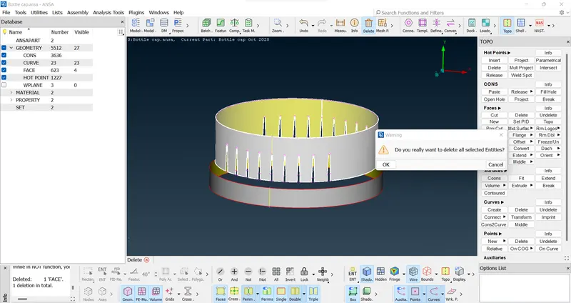
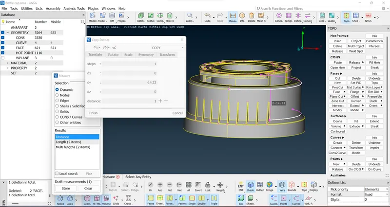
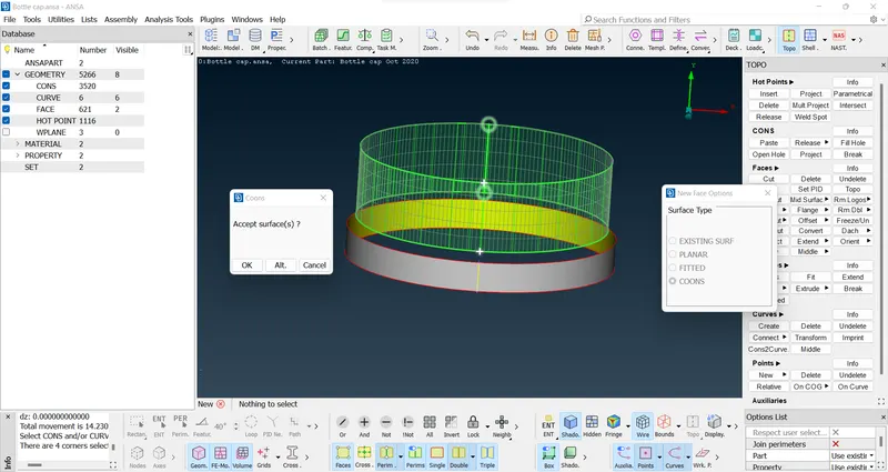
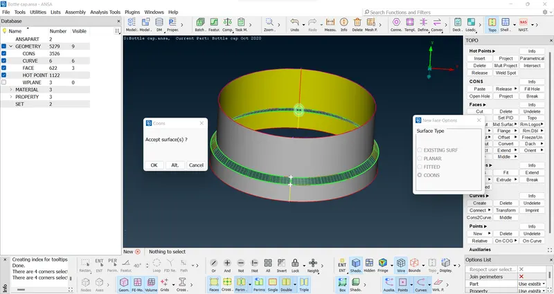
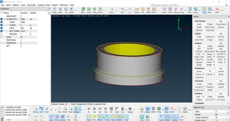
- The ribs are attached to the cover mid surface using TOPO > Faces > Extend function. The single cons that need to be extended to touch the surface are selected and next the surface to which the ribs need to be attached is selected and confirmed. This creates triple cons where rib sides get attached.
- And also for upper part of plate using offset.
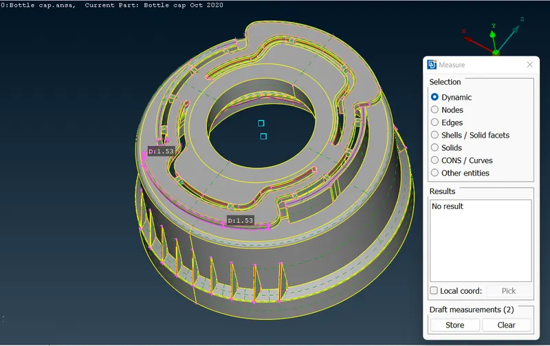
- This is the top part of the bottle cap. The areas with the thickness of 1.53 mm are only selected for Faces > Offset function and mid surface is generated with the offset value of -0.765 mm.
[NOTE: Also using Transform > copy >select the faces & in ‘Y’ direction 1.53/2 with a confirmation midsurface alternately created]
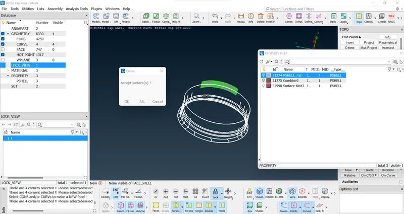
- The sidewall structure of the top surface is replicated in the form of mid surface by creating a middle curve using the top double cons of the wall.
- The curve is then projected to the bottom plate using Cons > Project
- Both: the curve and projected con is selected for creating a new surface using New (COONS) function in Faces.
FINAL MIDSURFACES:
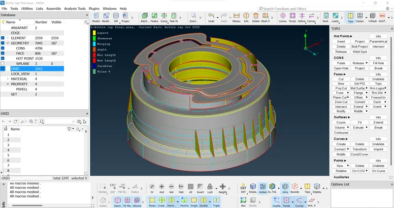
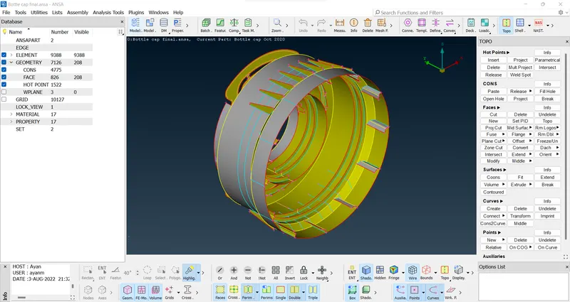
MESHING:
Setting the quality parameters:
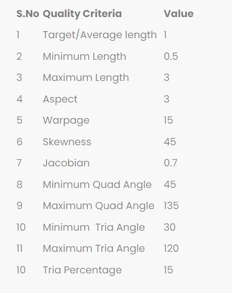
- The given quality parameters are fed to ANSA by going to Menu Bar > Utilities > Quality Criteria, selecting the required quality checks and entering the values as shown below:
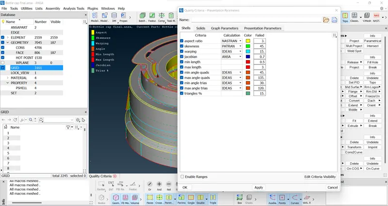
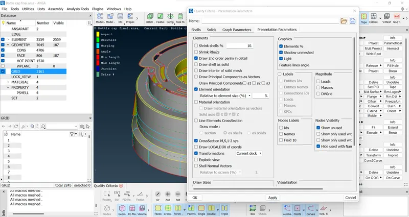
- Aspect ratio demands the maximum length of a side of a mesh element should not be greater than 3 times the minimum length side
- Skewness demands the element shape to be good based on the interior angles of the quad and tria elements
- Warping demands that if the quad element is bent into 2 planes then the angle made by the plane normals to not exceed 15 degrees
- Jacobian demands the mesh elements to be of ideal shape with small tolerance
- The mesh elements side length should be in the range of 0.5 mm to 3 mm
- Triangles % sets the requirement that of the total mesh elements the trias should not exceed 15 %.
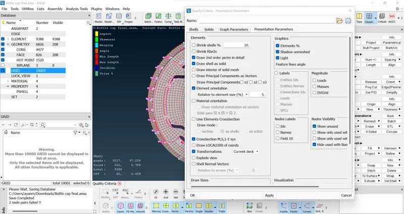
In quality criteria >presentation parameters > elements % should enable.
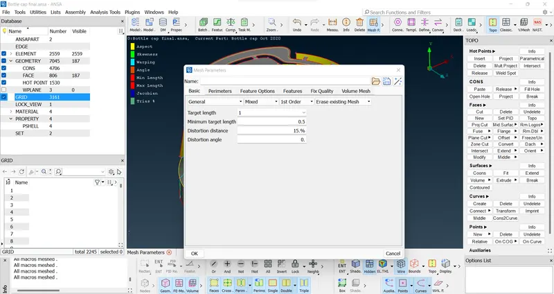
- The mesh parameters set the guidelines to be followed by the meshing algorithms by specifying the above-shown parameter in Menu Bar > Utilities > Mesh Parameters
- The idea side length of the mesh elements is set to 1 mm
- The mesh type is set to general and mesh elements can be a mixture of quads and trias.
Defeaturing the geometry: Since the minimum thickness is 0.5 mm, some area with close Coons are fails for meshing quality criteria. Hence it is defeatured by joining lines using TOPO > Faces > Cut & right click over the line. (make sure to maintain the feature line while Defeaturing.)
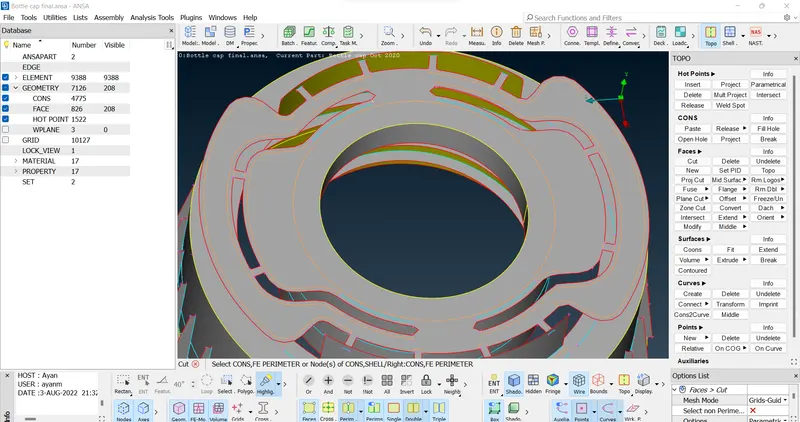
Also in extended inner ribs section with cylinder, a little gap left in lower edges , To avoding quality criteria fails usin cut upto the edge > insert a hotpoint in ribs and create a new face over there (after perform cut the unnecessary cons.)
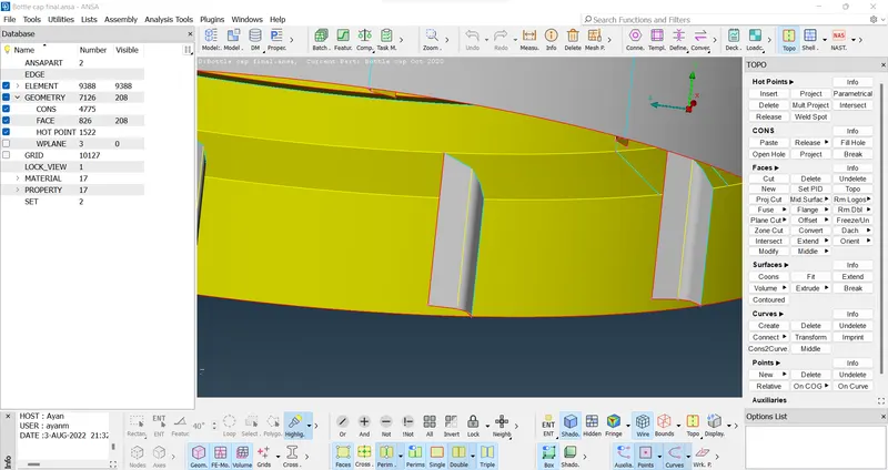
Performing Meshing:
- The deck is switched from TOPO to MESH
- From the MESH deck, nodal length is set to 1 mm for perimeters and macros from Perimeters > Length
- The visibility is switched from Shadow to Hidden mode
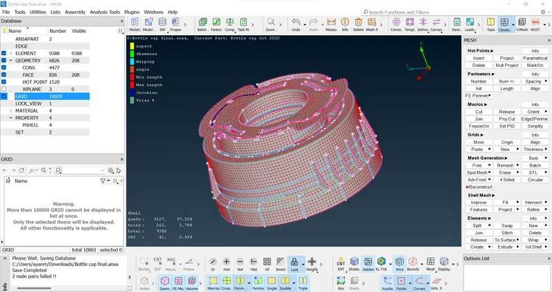
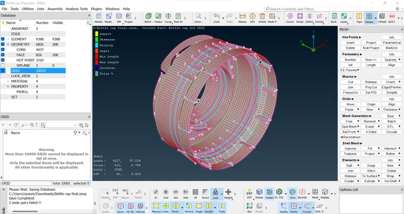
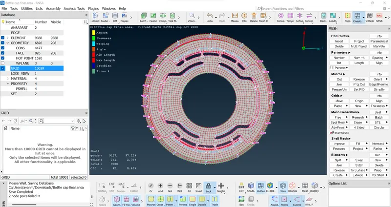
- The macros areas are selected and Best mesh algorithm is applied from MESH > Mesh Generation > best
- And also using spot Mesh Generation > spot mesh .
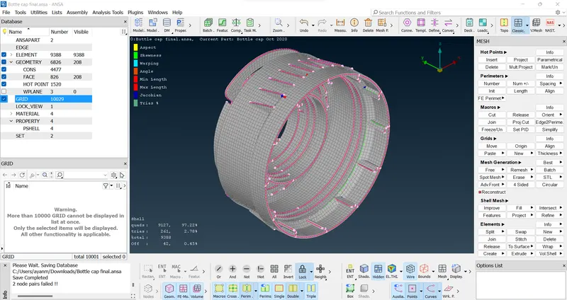
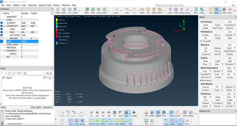
- After mesh done click shell mesh > improve > reconstruction / smooth / reshape / fix quality also performs for better mesh flow & to eliminate the OFF elements.
- The following rotating quad was generated. Since it is unaccepted, it is eliminated using MESH > Elements > Split function.
- The Split cases window pops up. Nodes is selected and the opposite sides of the rotating quad is selected and confirmed. This divides a quad into triangles.
- Also use swap / paste / join for fixed trias.
DRAW SHELL AS SOLID:
- Setting PID & Thickness to various components of bottle cap :
- Set PID function in TOPO > Faces > set PID is used .
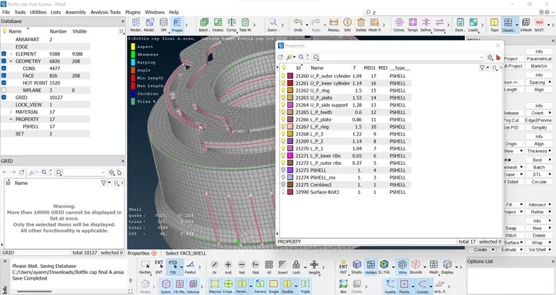
- Selection window appears. Individual faces are selected and confirmed. The Property card appears. (ctrl+P to check properties)
- New PID is generated for the particular face by right-click > New > PSHELL. In the PSHELL window, name of the face is fed and the corresponding thickness.

Quality check:-
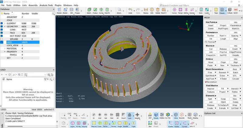
The meshed part can be checked for quality criteria by switching the drawing styles to hidden mode
The meshed part can be checked for quality criteria by switching the drawing styles to hidden mode, at some areas where two different triple cons are present the elements fail due to minimum element length which cannot be solved, hence there are some off elements present in the model.
Learning Outcomes:
- The unwanted nodes and cuts in the mid surface contribute to failed mesh elements after meshing. After the extraction of mid surface, unnecessary hot points are removed using TOPO > Hot points > Delete and unnecessary cuts joined using TOPO > Faces > Cut and right-click.
- The necessary modifications are to be done before the mesh generation. Any modification done to the topology after the mesh creation results in mesh deletion. This results in tremendous increase in meshing time.
- If Extend function is not working with an edge of a face, then new face is generated instead and Intersect function is used.
- While extract Mid surface with three different methods by using middle curves and create new faces(note: also use cons2curve,connect curve multi ), select the face and using Transform option >copy the face > diameter/2, and also using offset > direction + diameter/2.
CONCLUSIONs:
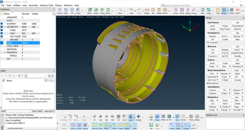
The bottle cap is successfully meshed with 42 OFF elements. The trias formed were 2.78 % that is less than maximum limit of 15 %. Draw shell as solid is enabled in Elements field of Presentation Parameters in Quality Criteria card.
FINAL MODEL LINK:
https://drive.google.com/file/d/13y_WoYTUNX5HVLffdQodFws_JcAXr03E/view?usp=sharing
https://drive.google.com/file/d/13y_WoYTUNX5HVLffdQodFws_JcAXr03E/view?usp=sharing