Week - 4 - 2D meshing for Plastic components
AIM
|
TO CHECK FOR GEOMETRICAL ERRORS OF PLASTIC BOTTLE CAP MODEL MID SURFACE EXTRACTION USING BEST POSSIBLE COMMAND TO DECREASE TIME OF PREPROCESSING. MESH GENERATION OF UNIFORM FLOW THROUGH OUT THE MID SURFACE OF CAD GEOMETRY AS GIVEN MESH PARAMETER AND QUALITY CRITERIA. |
OBJECTIVE- For the given Plastic Bottle Cap model, check for the geometrical errors and take the mid surface by suitable mid surfacing techniques. PID and Thickness assignment has to be done for all the mid surfaces. Mesh the same with given element Quality criteria.
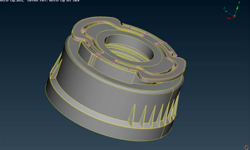
PROCEDURE
STEP 1: Import CAD geometry of STEP file using ANSA File tab in ANSA Window.
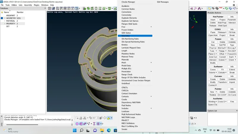
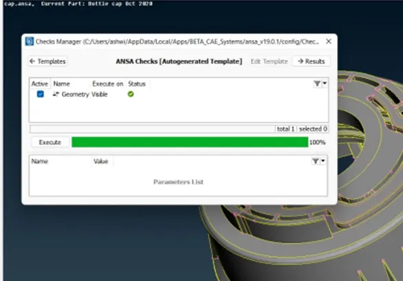
Proceeding for geometrical checks of CAD model through checks manager .
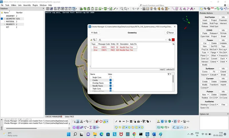
ANSA Checks manager shows total 2 needle face error .
we can highlight any of the problematic areas by left-clicking on it, or isolate it on the screen by right-clicking on it and selecting “Show only”. Depending on the type of the problem ANSA also offers the option to automatically fix it.
ANSA can automatically fix these geometrical errors but for analytical purpose we are going to fix these geometrical errors manually.
Needle face error is just a error arises due to coincidence of cons of opposite faces. We can simply delete that needle face from choosing appropriate face id.
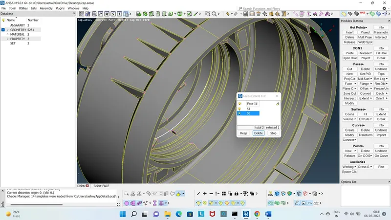
After deleting the needle face id, we can perform topology to stich sharing edges and features lines. Or we can automatically fix errors by auto fix option.
STEP2:
After checking geometry, orientation, and topology of given cad model we can proceed for mid-surface generation by measuring thickness of all features of model.
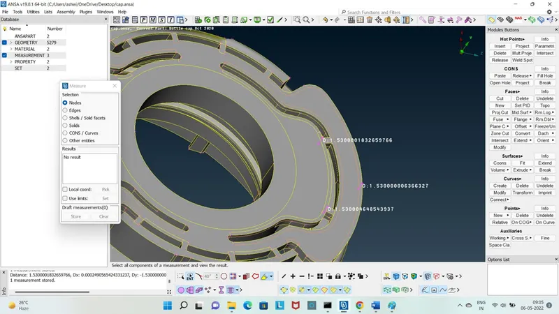
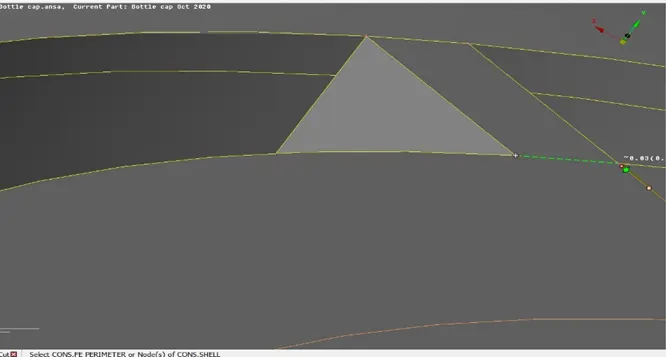
To capture all feature area in mid surface generation, we can draw project cut lines according to requirement of geometry and shape of component.
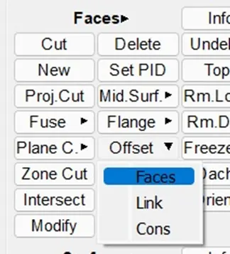
In context of taking mid surface of top part of given cad model, we can offset its faces to middle of its total thickness in opposite direction of offset vector direction, therefore we take negative sign.
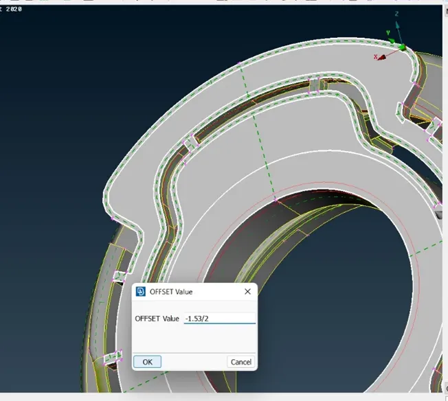
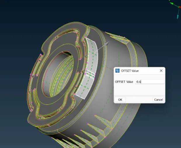
In similar way, after measuring thickness we can offset slected faces
In middle of its total thicken
ss zone.
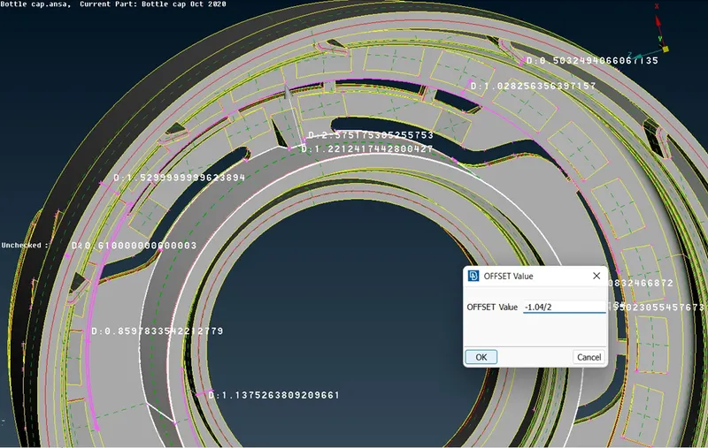
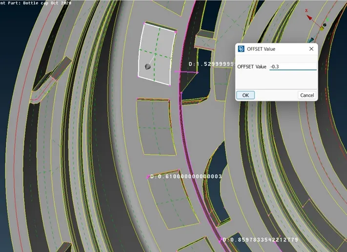
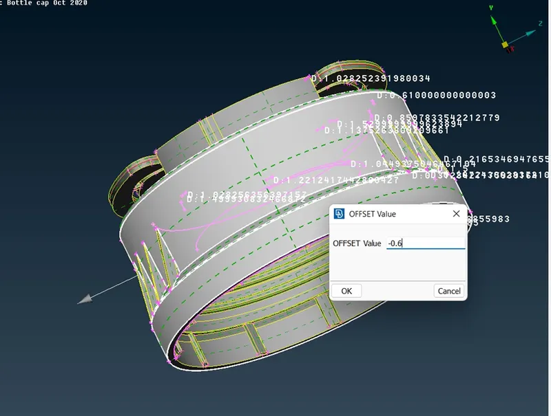
All feature area should be carefully slected to take exact offset of
Faces.
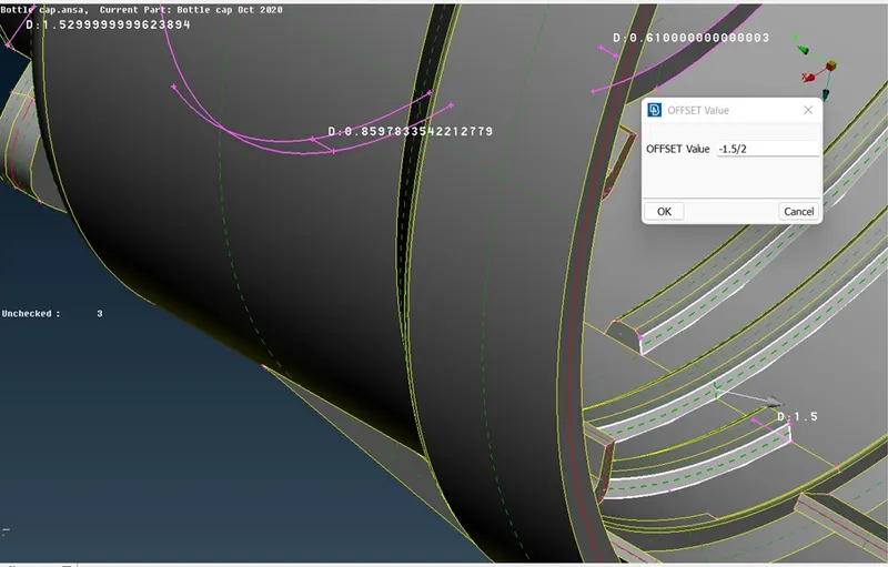
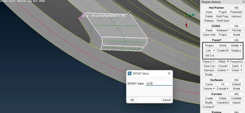
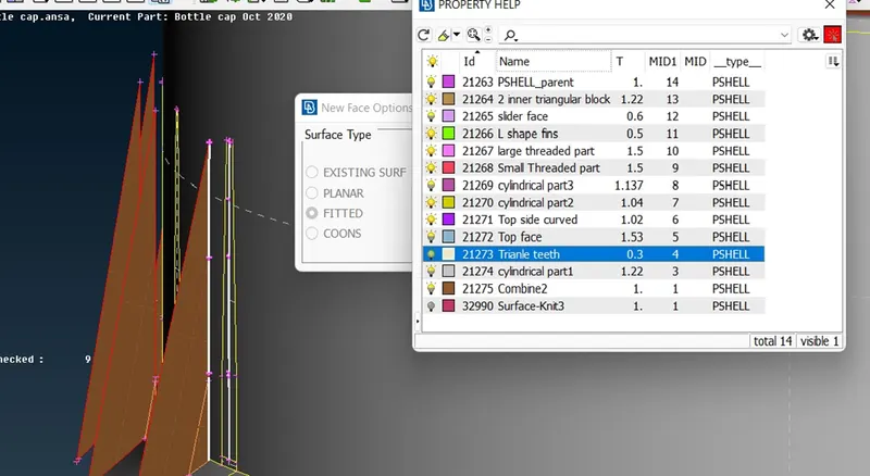
STEP 3: After generating mid surface of all components of model, we can assign PID property ID and assign respective thickness value to mid surfaces.
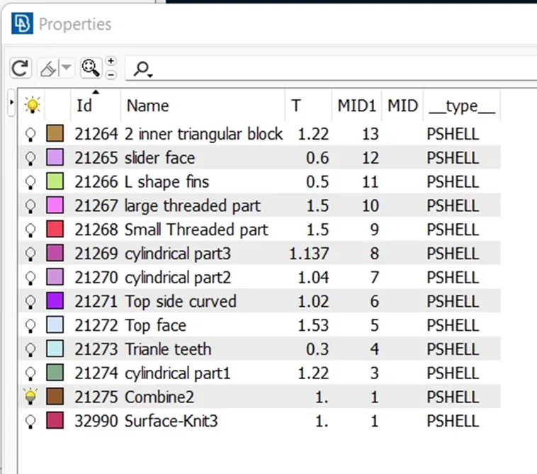
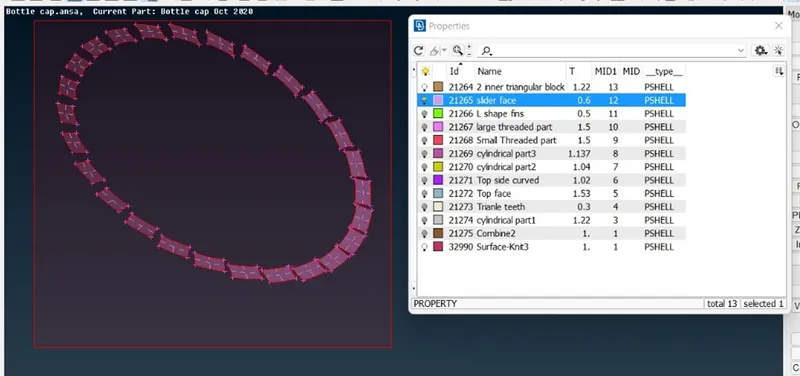
Slect the area where PID have to assign or we can slect faces individually in case of precision work.
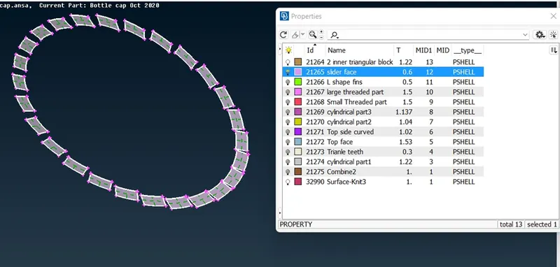
After slection of faces where PID have to assign, press ENTER to execute the process.
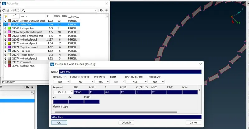
Then we can assign thickness of component with respect to measurement of thickness between two nodes.
Similarly, we can assign PID and respective thickness of each component.
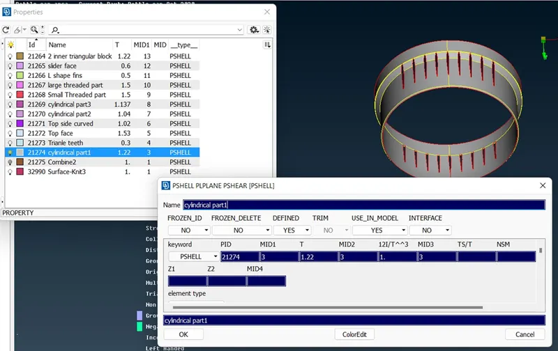
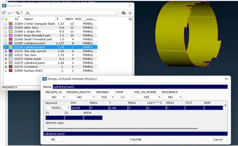
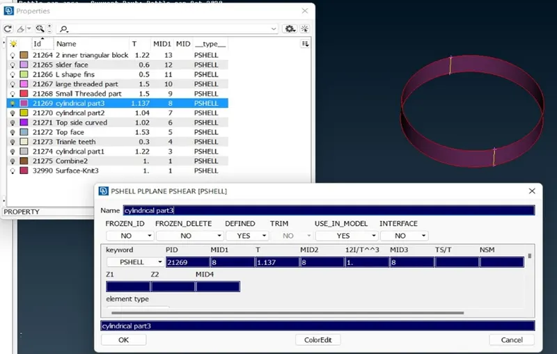
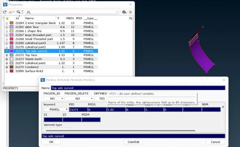
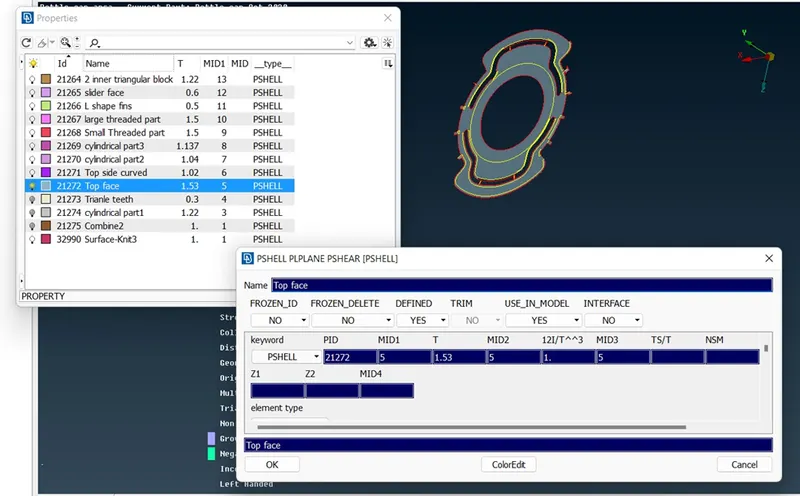
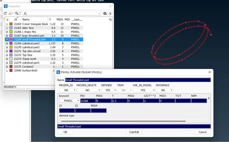
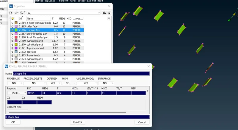
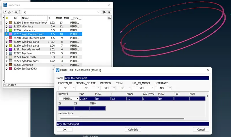
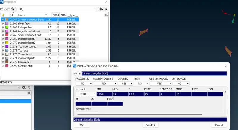
STEP 4: After assigning PID and thickness to each component of mid surface, we can proceed to attach all independent entities as a one integrated model.
To attach different entities ,
We have to project cons to that surface where attachment has to made.
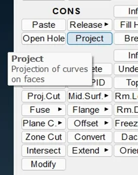
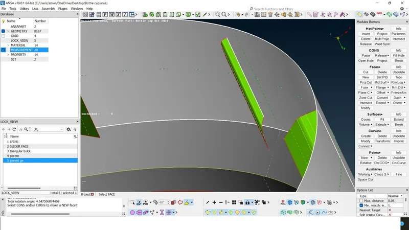
To project con slect con and surface where projection is to made.
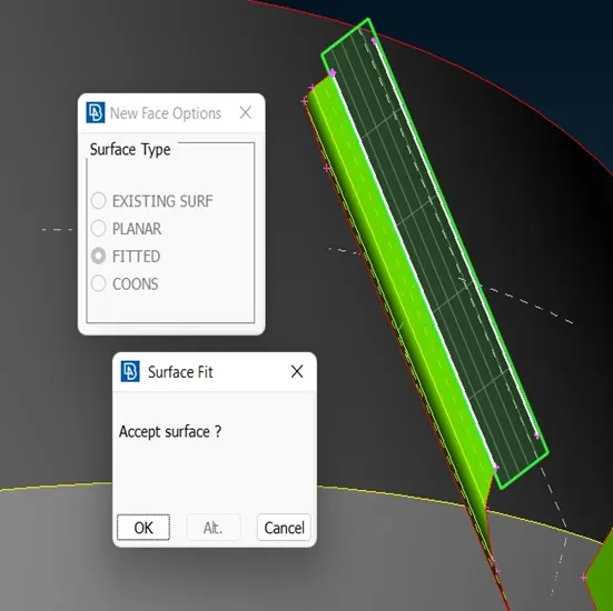
Then we can create surface between projected con and original entity’s con.
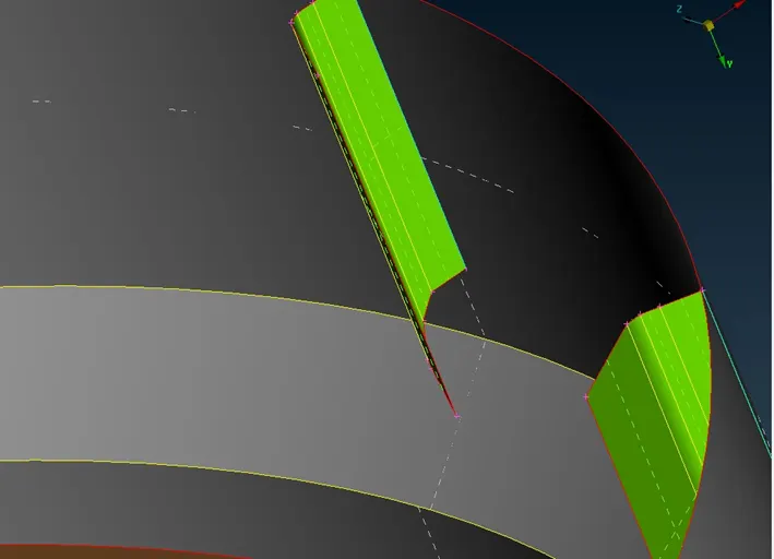
On pressing OK
Surface is successfully generated between entity’s con and projected con.
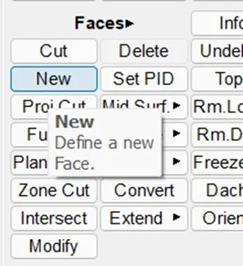
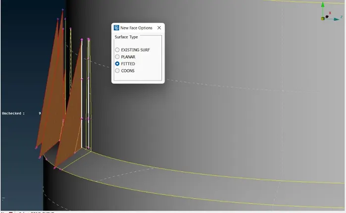
Gap between any surfaces can be filled by using New surface command option.
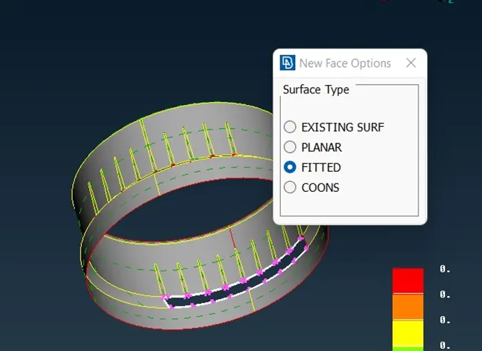
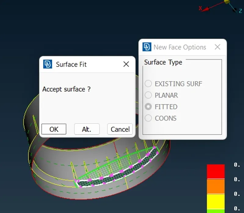
On accepting surface on
Green net curve ANSA will generate new surface perfectly.
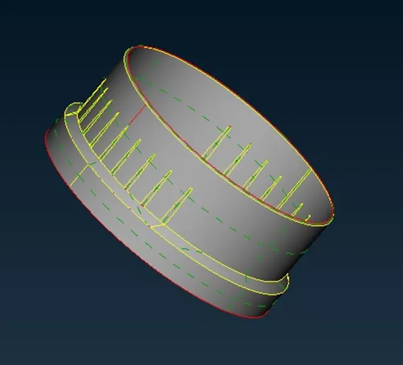
Similarly , we can attach all independent entities together as one integrated model
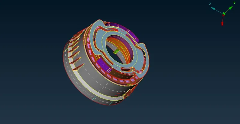
STEP 5: After assembling all mid surfaces as a one integrated model, we can now proceed for Mess generation process.
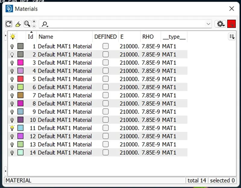
Review for type of material before mess generation is important aspect for solver and simulation process.
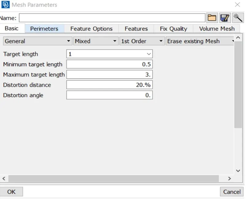
Then mess parameter should be properly input according to given data.
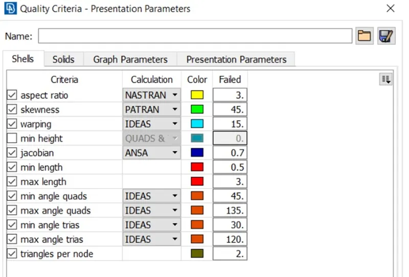
Quality criteria tab can be also open by F12 key.
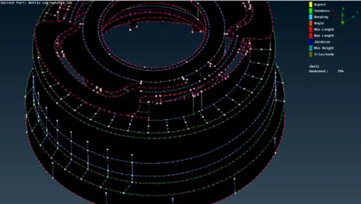
Project cuts are made on model at different sections, which helps ANSA in uniform distribution of mess flow.
Since, now we can proceed for mess module operatons for each components and features independently
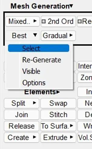
ANSA can generate better mesh by BEST MESH command option.
Mess improvement tool, such as RECONSTRUCT, RESHAPE, SMOOTH, FIX QUALITY are powerful mess generation tools in less duration of time.
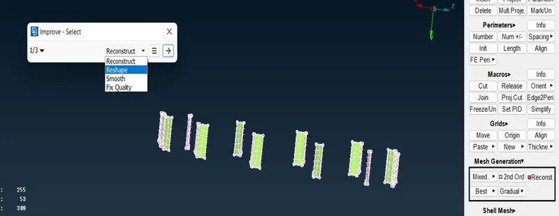
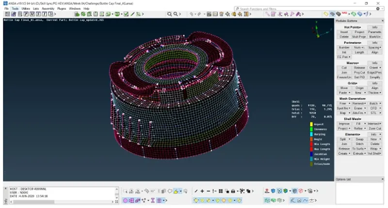
Similarly, we can generate mess on each and every mid surfaces features separately to obtain better and uniform mess flow.
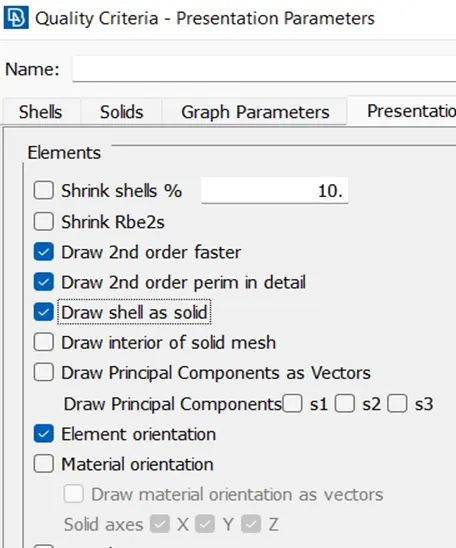
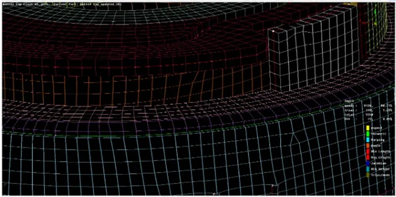
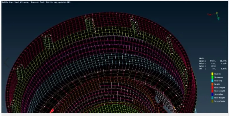
From Quality criteria tab we can apply on Draw shell as solid to visualize assigned thickness of each mid plane of cad model.
Learning outcome
1: learned new approaches of mid surface generation and mess improvement.
2: Got more clarity of concepts .
- learned better and smart application of tools.
CONCLUSION:
We can conclude that model is successfully messed after geometry cleanup, topology and mid surface generation.
Some elements were unable to pass mess quality criteria. Minimum length of feature lines and skewness can be improve before final analysis of model.