Week - 4 - 2D meshing for Plastic components
Week 4
For the given Plastic Bottle Cap model, check for the geometrical errors and take the mid surface by suitable mid surfacing techniques. PID and Thickness assignment has to be done for all the mid surfaces. Mesh the same with given element Quality criteria. (Refer the table Below for the Quality criteria)
|
S.No |
Quality Criteria |
Value |
|
1 |
Target/Average length |
1 |
|
2 |
Minimum Length |
0.5 |
|
3 |
Maximum Length |
3 |
|
4 |
Aspect |
3 |
|
5 |
Warpage |
15 |
|
6 |
Skewness |
45 |
|
7 |
Jacobian |
0.7 |
|
8 |
Minimum Quad Angle |
45 |
|
9 |
Maximum Quad Angle |
135 |
|
10 |
Minimum Tria Angle |
30 |
|
11 |
Maximum Tria Angle |
120 |
|
10 |
Tria Percentage |
15 |
ANS:-
I have followed no. of steps as follow to complete the bottle cap meshing.
1. Geometry check
2. Mid surfacing
3. setting length of elements.
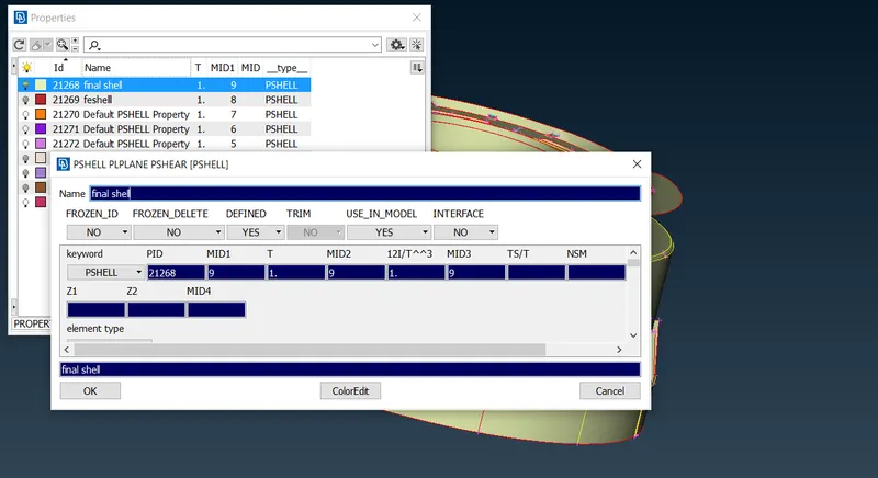
3. assigning thickness.
4. setting given quality criteria.
5. meshing the model.
briefly discussing above steps as below.
1. geometry checkup:- geometry checkup done with ticked parameter listedd in following pictures
found issues with tripple cons crack and overlap and resolved by usin auto fix option.
we have obsorved 100 % ok for geometry check
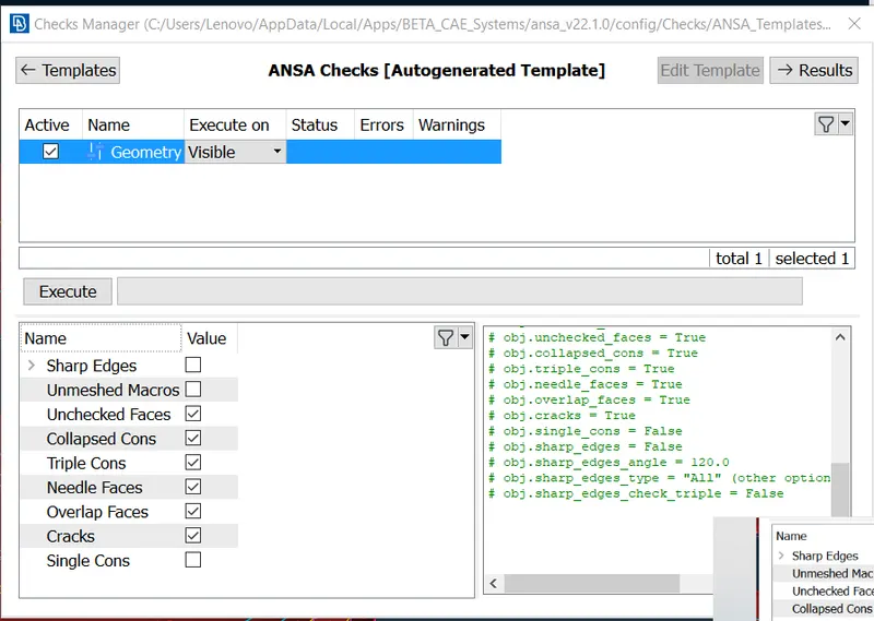
2. MIDSURFACING:-
1. surface thicknesses checked and recorded to perform offset command.
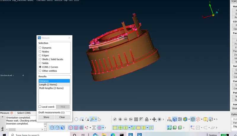
2. midsurfaacing done manually using offset command in topo.
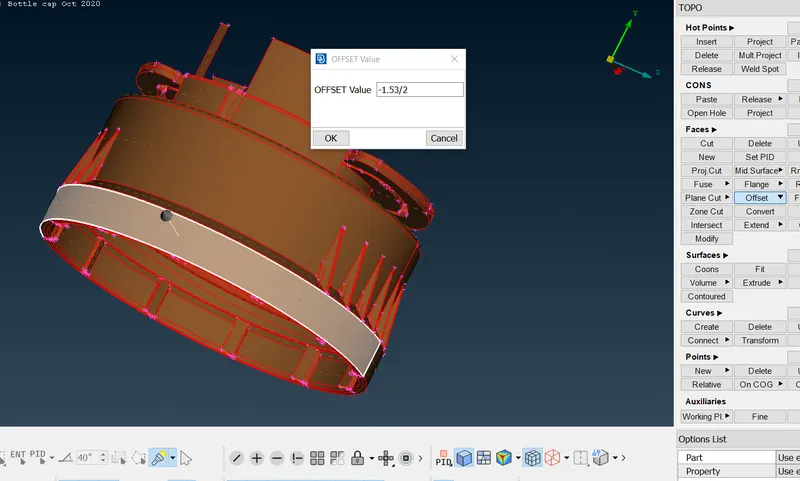
3. at critical surfaces like teeth and threads middle option in curve used to get middle curve.
4. middle curve is obtained by selecting to cons of threads.
5. then project in coons is used to find cons parallel on the base surface.
6. surface is obtained between two cons to get the middle face for the threads.
7. for teeths above procedure is used for single teeth and then copied the same with transform command.
8. all parent geometry deleted and only middle surface is kept for meshing.
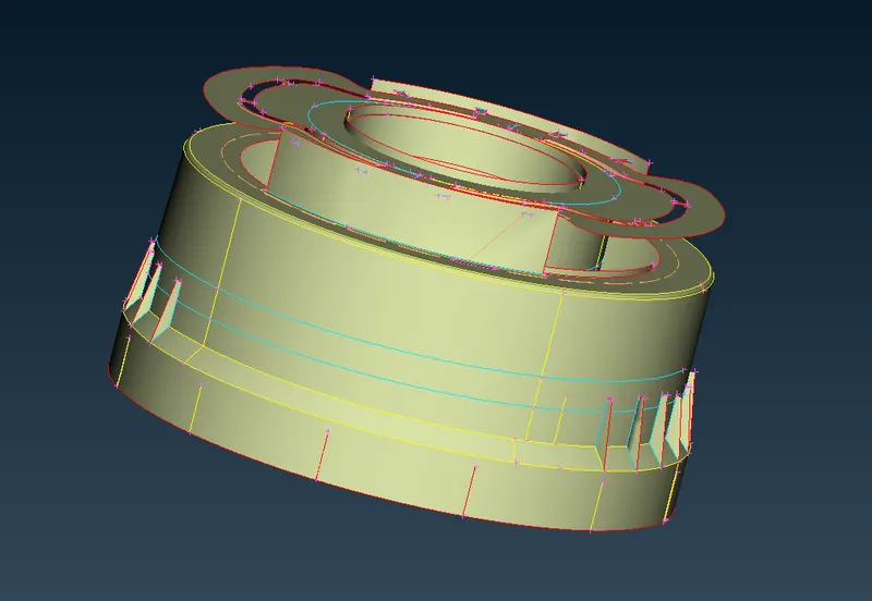
9. again geometry check done to ensure any geometrical issues .
3. setting length of elements:-
---length of element is set for 0.5
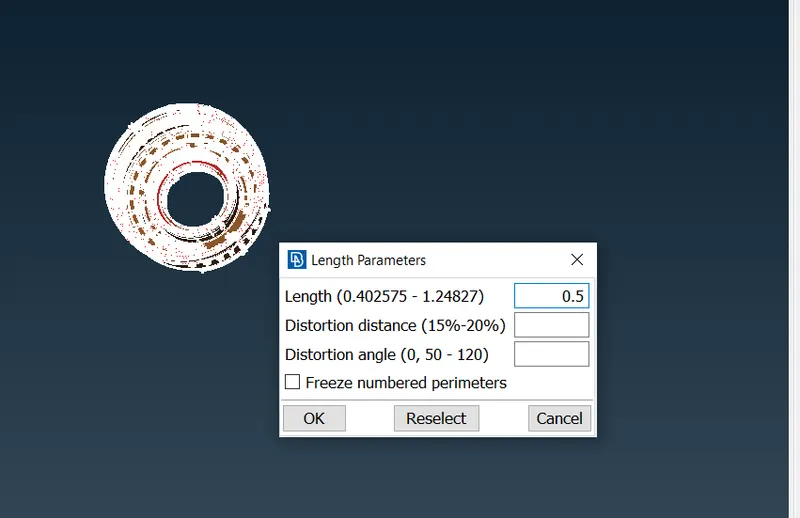
3. ASSIGNING THICKNESS :- thickness is assigned as below picture in property identification.
4. SETTING QUALITY CRITERIA :-
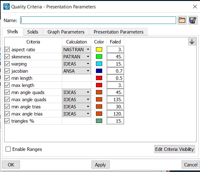
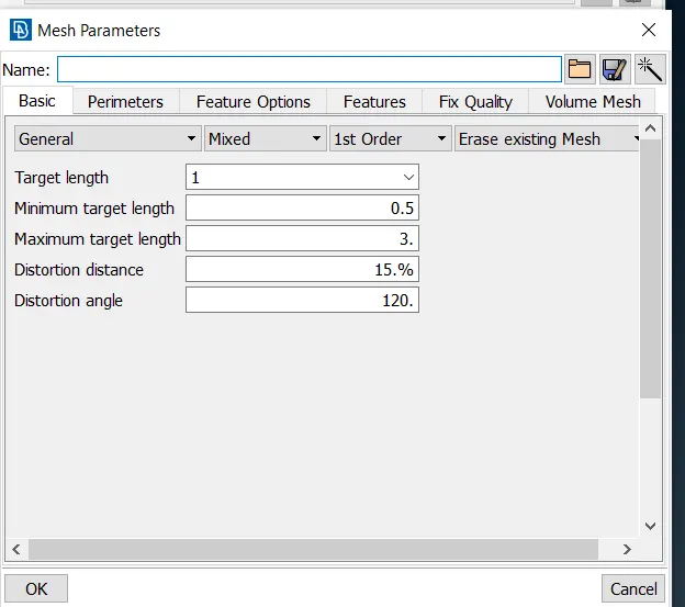
5 MESHING THE MODEL :-
1. meshing is done with best command in mesh generation.
2. many faults observed, reconstruction command used to reduce possible faults.
3. 100+ faults still observed checked all the faults solved to least manually.
4. multiple commands used to ensure 0 faults.
5. split, swap, paste, smooth, reconstruction, Grid move.
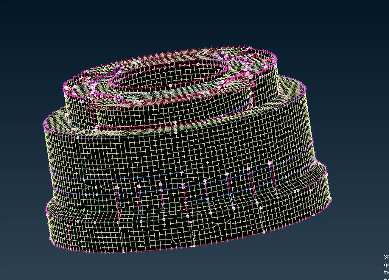
--outcomes from this challenge:-
1. multiple commands function learned and practised well.
2. manual mid surface extracting practised well.
3. practised well to ensure good quality of mesh.
-
The Tria elements should never be opposite to each other
-
No Tria elements should be connected back to back
-
No Tria elements should be on the edge of the geometry
-
No Tria elements should be near the holes
-
No Tria elements should be on the feature and the fillets.
-
There should be less Tria concentration, i.e., there should be a considerable distance between Tria elements.